Yes - waiting is no fun. One of my biggest reasons for building amps from scratch is that parts are all readily available and projects take maybe a day of two to build once parts are in. If you have a good stock of basic parts and transistors you can make 90% of the amp designs posted one you secure a PCB or go P2P.
Waiting for a bolt is no fun. Seems like such a basic part. I use Space drywall screws to hold together most of my speaker projects.
Waiting for a bolt is no fun. Seems like such a basic part. I use Space drywall screws to hold together most of my speaker projects.
It was a nice day today and gave me a great opportunity to work on these cabinets. Well, I was able to successfully add a centering disc by screwing a small plywood square from the back. Routed the rebate to correct diameter and depth. Perfect actually. It all fits and I can proceed to adding internal dampening and mounting drivers. Hopefully a sound check tonight and maybe fire it up with minidsp as a two way xo. Should be interesting - really wondering how well these passive radiators work. I have heard other speakers with PR's before and they were impressive. Some Polk Audio standpoints from the 1990's. Also with 6.5in driver and dome tweeter.
Progrress
Installing Noico sound dampening sheets inside box:
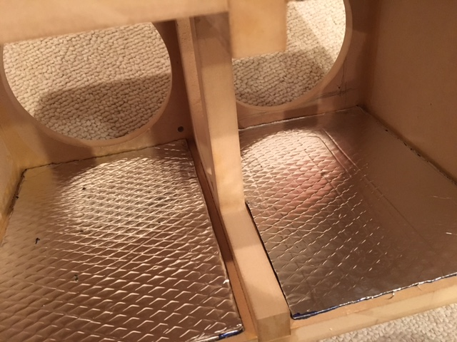
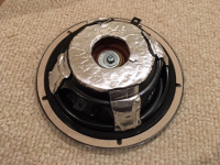
Installiing Noico on metal basket of PR (this really transformed a tinny bell like sound to a thud when tapping the basket):

Installing 1in Sonic Barrier foam on internal walls (I did 4 walls except front and back):
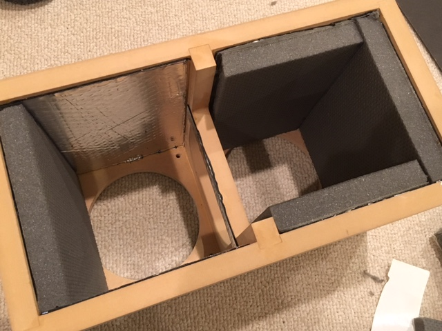
Sound dampening scheme on front baffle (adding Noico to plastic WG really helped to deaden its sound when tapped, also addef to tweeter rear chamber):

Gluing baffle and clamping with ratchet tiedown straps:
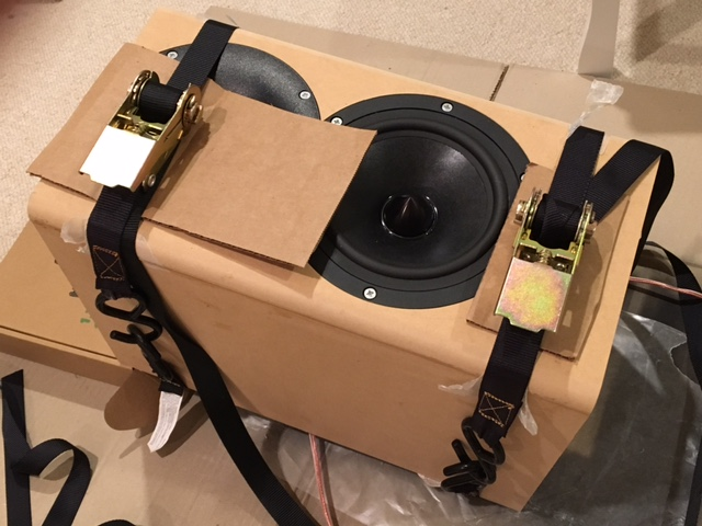
I have two speaker cables going through the two holes for the binding posts for purposes of measuring raw response and also to test with miniDSP as active 2 way. I know it's airtight because pushing on driver cone makes PR cones push out.
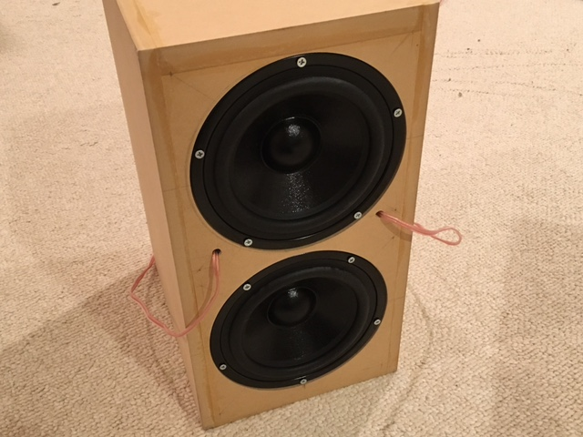
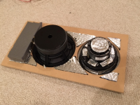
Passive radiators mounted, about to test first sound:
Installing Noico sound dampening sheets inside box:
Installiing Noico on metal basket of PR (this really transformed a tinny bell like sound to a thud when tapping the basket):
Installing 1in Sonic Barrier foam on internal walls (I did 4 walls except front and back):
Sound dampening scheme on front baffle (adding Noico to plastic WG really helped to deaden its sound when tapped, also addef to tweeter rear chamber):
Gluing baffle and clamping with ratchet tiedown straps:
I have two speaker cables going through the two holes for the binding posts for purposes of measuring raw response and also to test with miniDSP as active 2 way. I know it's airtight because pushing on driver cone makes PR cones push out.
Passive radiators mounted, about to test first sound:
Attachments


Last edited:
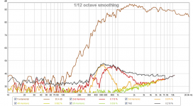
Although glue had not dried yet, an initial frequency response measurement showed a nice amount of bass extension with a shallow falloff slope much like a sealed alignment. I don't have any stuffing yet so things should improve some more. I did see a hump in HD around 1.2kHz. This corresponds to a half wave resonance of 6.1in - about same as distance from woofer to PR basket flat surface. So probably need to add felt or foam on the basket face of passive radiator. Overall looks good and an impressive amount of bass output could be seen and heard coming from the two radiators in the back. They really move. Will post data once I take measurements with glue dried. The HD on the WG tweeter seemed to have improved with addition of Noico sound dampening sheets on driver rear chamber and on WG. HD is consistently low at -45 to -50dB at normal listening SPL.
Awesome progress!
I just ran across this, a little late:
Tips and ideas Copyright 2012-14
Part way down the page: "MAKING A DRIVER HOLE BIGGER"
I just ran across this, a little late:
Tips and ideas Copyright 2012-14
Part way down the page: "MAKING A DRIVER HOLE BIGGER"
Awesome progress!
I just ran across this, a little late:
Tips and ideas Copyright 2012-14
Part way down the page: "MAKING A DRIVER HOLE BIGGER"
That's exactly what I did. I screwed a plywood plate from the back though.
Raw Measurements
Here are the raw measurements at 0.5m distance and 1.00v rms using calibrated UMIK-1.
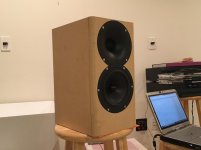
Photo of setup:

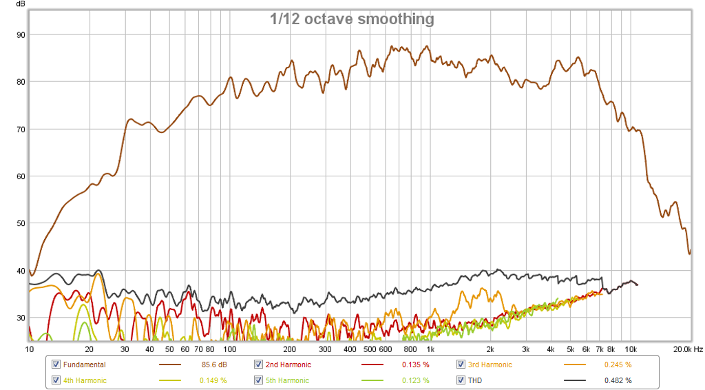
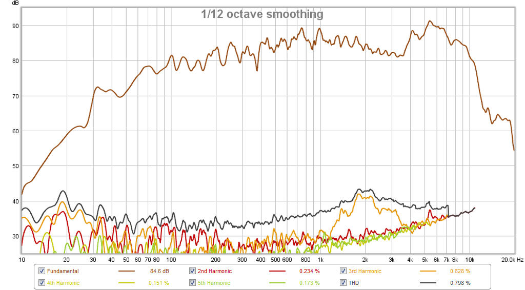
Raw frequency response of RS180P-8 on woofer axis. Not 2kHz H3 distortion peak ???:

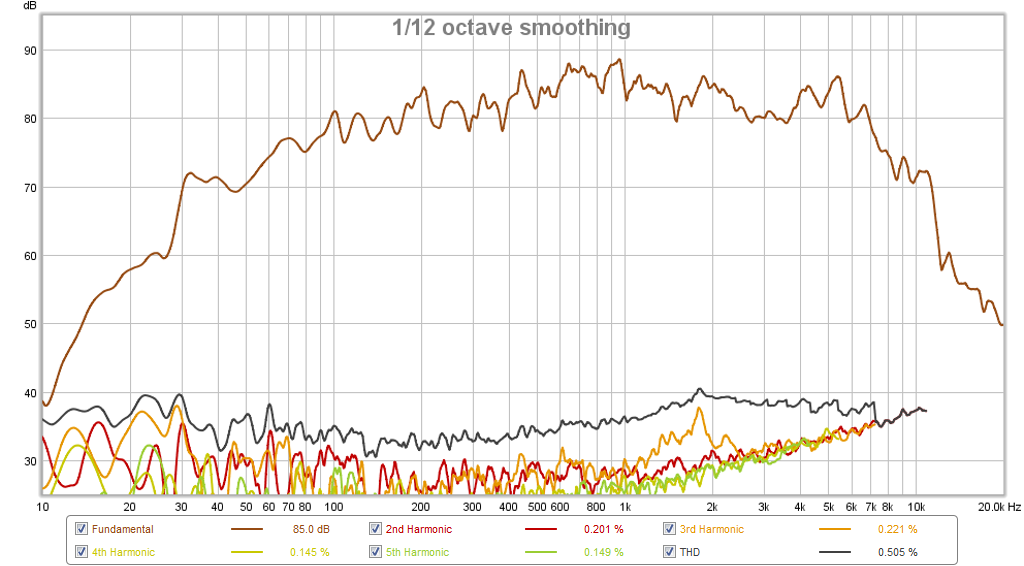
Raw frequency response of RS180P-8 on tweeter axis:
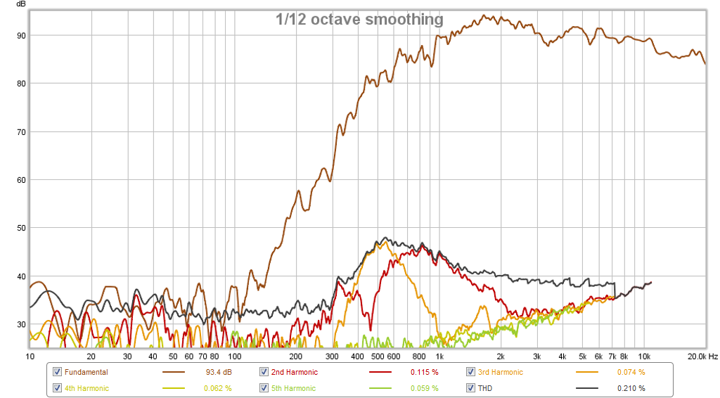
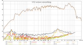
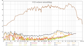
Raw frequency response of RS28F in waveguide with 50uF protection cap:
RTA at 2kHz showing harmonic distortion components are real and not just noise:
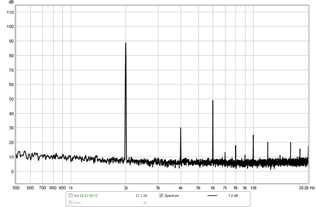
So now onto debuging source of 2kHz H3 peak... if anyone has any ideas what could be causing this please let me know. I suspect it may be airflow between the WG and the adapter plate forming a 1.6in long radial 1/4=wave resonator?
Here are the raw measurements at 0.5m distance and 1.00v rms using calibrated UMIK-1.
Photo of setup:
Raw frequency response of RS180P-8 on woofer axis. Not 2kHz H3 distortion peak ???:
Raw frequency response of RS180P-8 on tweeter axis:
Raw frequency response of RS28F in waveguide with 50uF protection cap:
RTA at 2kHz showing harmonic distortion components are real and not just noise:
So now onto debuging source of 2kHz H3 peak... if anyone has any ideas what could be causing this please let me know. I suspect it may be airflow between the WG and the adapter plate forming a 1.6in long radial 1/4=wave resonator?
Attachments

Second woofer test
I swapped out the RS180P for another unit, and sealed the gap between the WG and the 3D printed adapter. Another set of HD measurements shows that the high H3 distortion is still present, albeit a slightly lower level. This leads me to believe that this distortion is inherent in the RS180P. Does anyone else have a distortion measurement?
Measurement on woofer axis:
Measurement on tweeter axis:
I opened up the back by removing one of the PR's to basically resemble an open back or open baffle speaker to eliminate air compression as a source of HD. It is still there so inherent in this driver:
Attachments

Last edited:
If anyone else has used RS180P-8 before, have you noticed this H3 rise at 2kHz? Maybe it's not really an issue if I have a 1.7kHz -12dB/oct low pass filter?
I listened to it a bit with a crude crossover and sounds very good despite this. The bass is quite present but much of it is directed out the backside as result of passive radiators. Placement a little closer to back wall will really reinforce the bass. One thing I notice about passive radiators is that the bass is deep and fast without any port noise. Group delay measurements shows -3ms at 50Hz and -2ms at 100Hz so resembles a sealed alignment. Very good for basis of a transient perfect speaker. It's also interesting how both passive radiators seem to move more than the amount of stroke that the single woofer exerts on them. Almost like there is an amplification due to the resonance amplification - which should in theory minimize the cone excursion on the woofer for lower harmonic distortion.
I listened to it a bit with a crude crossover and sounds very good despite this. The bass is quite present but much of it is directed out the backside as result of passive radiators. Placement a little closer to back wall will really reinforce the bass. One thing I notice about passive radiators is that the bass is deep and fast without any port noise. Group delay measurements shows -3ms at 50Hz and -2ms at 100Hz so resembles a sealed alignment. Very good for basis of a transient perfect speaker. It's also interesting how both passive radiators seem to move more than the amount of stroke that the single woofer exerts on them. Almost like there is an amplification due to the resonance amplification - which should in theory minimize the cone excursion on the woofer for lower harmonic distortion.
Last edited:
I can't help you directly as I don't have an RS180, but it seems strange that the distortion seems to peak at around 1.8Khz but is quite different on the tweeter axis. Although the frequency response is different between the two graphs it doesn't seem to account for the difference in distortion. Did you get the same sort of thing in your Bookshelf Horn with those drivers or did the bandpass filter it out? Is there any issue in the impedance plot around that frequency?
Even if you can't work it out by the time you have the crossover in place it will likely be suppressed more and it's already somewhere around -40dB so I doubt it will be too objectionable.
Even if you can't work it out by the time you have the crossover in place it will likely be suppressed more and it's already somewhere around -40dB so I doubt it will be too objectionable.
On bookshelf horn, bandpass holes filtered it out and I don't recall seeing it. XO on that horn was 600Hz.
The HD at 2KHz is the 3rd harmonic of the break-up peak at 6KHz. You can see that the HD closely mirrors the higher frequency response. That's why the HD drops when listening off axis; the woofer is beaming at that frequency.
The fundamental is at 2KHz, which is where you are measuring the distortion. Look at the curve for the HD, you can see that it mimics the frequency response 3x higher.
This is why it's not enough just to attenuate breakup, the corresponding HD peak at lower frequencies also needs to be taken into account.
This is why it's not enough just to attenuate breakup, the corresponding HD peak at lower frequencies also needs to be taken into account.
Last edited:
I see the resemblance in the breakup peak at 6k and the HD at 2k. But which causes which? The breakup peak at 6kHz occurs due to the mechanical design - I don't know how something can have a sub-harmonic signature. That is, a 6kHz having a 1/3 x f subharmonic at 2kHz.
I still find it very odd that the shape of the harmonic distortion is the same as breakup peak. Could this be some sort reflection anomaly? I don't see how the shape of the HD drives the shape of the resolve breakup? I wonder if it's some sort of setup error on my part?
It's not a sub-harmonic, it's straight-forward HD. If you have a fundamental tone at 2KHz, your 3rd harmonic will be at 3KHz. Now if you have a peak in your response at 3KHz, you will correspondingly have a peak in HD3. This is exactly what we are seeing. HD is a function of frequency response, and other things too of course.
Try going over to Zaph's place and comparing frequency response with HD3 and HD5 for various drivers. Some show it very clearly, others less so.
There's no error in your setup. To get round this problem, you can either cross very low, or apply some sort of cone/surround damping to ameliorate the break-up.
Last edited:
I'll try to explain with a simplified model:
Lets say the distortion is only caused in the motor and the peak in response at 6KHz is only due to a particular bending mode of the cone.
If we then measure distortion at 2KHz, the HD3 in the motor will be amplified in exactly the same way as a normal 6KHz signal due to the bending mode of the cone.
- Home
- Loudspeakers
- Multi-Way
- RS28F-RS180P-B80 as Hole Filler 3-way