Re: Nein!!!!!!!
Manuel!!! Hopeless........ completely hopeless!!!! [slap on the head]
Jocko Homo said:Starting to make sense?
Maybe I need to change my avatar to John Cleese, standing in water up to his knees, asking what is wrong if he eats squirrel now and then.
Jocko
Manuel!!! Hopeless........ completely hopeless!!!! [slap on the head]
Re: Nein!!!!!!!
Got it. Thanks!! 🙂
Glad I asked...even if it makes me look dumber.
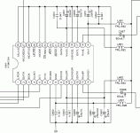
Jocko Homo said:I meant the gates with those numbers on the schematic..........!
You will have to then tie the inputs to them either high or low.
Starting to make sense?
Maybe I need to change my avatar to John Cleese, standing in water up to his knees, asking what is wrong if he eats squirrel now and then.
BTW..........that strange B-B DAC chip looks like they do the combining inside, so your cap mod should be ok. Providing you can deal with Solen.
Jocko
Got it. Thanks!! 🙂
Glad I asked...even if it makes me look dumber.
If I'm using Kwak or other 'already square' wave clock?
Hi Guys,
If I'm already using a Kwak clock or (Trichord2) that's presumably sending out a square wave already, do I need to bother inverting it at all? In other words, can I forgo using the HCU04's gates altogether and just send directly from clock out to the two resistors (mentioned aboved somewhere)?
Thanks. 🙂
Re: If I'm using Kwak or other 'already square' wave clock?
Yes!😎
ozone_stink said:Hi Guys,
If I'm already using a Kwak clock or (Trichord2) that's presumably sending out a square wave already, do I need to bother inverting it at all? In other words, can I forgo using the HCU04's gates altogether and just send directly from clock out to the two resistors (mentioned aboved somewhere)?
Thanks. 🙂
Yes!😎

Nice!! 🙂
Would you guys run 2 wires of equal length from the clock out to each of the resistors (above)?
I'm hard pressed to think of an alternative that makes more sense, but I'm not exactly batting 100 in this field.
Would you guys run 2 wires of equal length from the clock out to each of the resistors (above)?
I'm hard pressed to think of an alternative that makes more sense, but I'm not exactly batting 100 in this field.
Yeah of course if one wire is shorter those electrons will arrive earlier, sure..........
With huge impact on sound!😎
With huge impact on sound!😎

Getting rid of HCU04 is good here.
Well, thanks to the help of Elso and Jocko, I managed to remove the HCU04 from circuit.
Although I was worried that the speed of light would have an impact on the electrons flowing over different lengths of Cat5 wires, Heisenberg's uncertainty principle... Does God play dice?
Well, whatever, the sound was improved by running the wires from the clock out to the R633 & R635 -after pulling one leg of each resistor from HCU04 side of circuit. I kept the wires as short as possbile (to appease the RF Gods).
In terms of improvement, the best I can say is:
Prior to ripping the 'stock' crystal out of the oscillator circuit that included the 04 inverter, I was relatively happy with the sound of the Rotel CDP (but could not overcome my curiosity for the promise of better sound)
After replacing the crystal with the Trichord (and performing some 'other' mods listed previously in the thread) the sound was different...different bad, that is. I think I tried to pawn this off as 'not much difference' when really I knew better on some level.
I can happily say now that the sound with the Trichord2 and NO HCU04 is at least as good as stock (and I'm tempted to say better).
Less sibilance for sure. My 'Cinematic Orchestra - Every Day' CD no longer grates on my nerves.
I think the most important part of all this is the fact that now I feel quite confident in terms of placing the Kwak clock into my CDP (when it's finished being debugged / de-idioted).
If a little sarcasm is the price to pay for happy sound, then I'm still a customer. Thanks again for your help / patience. 🙂
Heaping on even more sarcasm........
See, if you hadn't spent all your money buying that squirrel.........
Just think how good it could sound if you had a real clock in there.
Sorry, Elso!
Jocko
See, if you hadn't spent all your money buying that squirrel.........
Just think how good it could sound if you had a real clock in there.
Sorry, Elso!
Jocko
Elso Kwak said:Solen fast caps will increase glare and harshness of CD sound, there another boutique part's money wasted!!!🙄
Hi Elso, a while back you had this to say... Assuming that I can't rip out this cap (DC present), would there be any value in considering the replacement of this cap with an electrolytic of higher quality...or is this still just a waste of money with possibly deleterious results?
Currently, it's a Panasonic FC cap. Possible replacements:
Panasonic FM
Elna Cerafine
Black Gate
NULL (don't know if this is wise).
In this circuit I was speaking about replacing the dc-blocking caps that are 4.7uF (50V) Panasonic FCs. (C667 & C668)
Is there any point or am I simply wasting time and money? I suspect that it would not be wise to replace these with 220uF anything (incl. Nichicon Muse.)
However, maybe I'm wrong...wouldn't be the first time.
Is there any point or am I simply wasting time and money? I suspect that it would not be wise to replace these with 220uF anything (incl. Nichicon Muse.)
However, maybe I'm wrong...wouldn't be the first time.
Attachments
Hello
It looks like you have a black Solen (metallized polypropylene -yaky). You can try the white ones - polypropylene, like a 0.68uF(part number SM068).
I'm sure that this won't really solve your problem so you can adjust your bazooka for Cote St-Luc
There's more RF than the Marantz can digest. Probably you need to revert to an active filter of sorts. If you choose the original: my first choice would be to lower C701/702 from 100pF to mica ~ 22pF or so. And then to keep the AD8620, some film caps for C667/668 and Elnas at the output.
Of course first you must place the heart on the right side - install a nice clock and decoupling caps....
OK, I'm out to search for a:
ozone_stink said:In this circuit I was speaking about replacing the dc-blocking caps that are 4.7uF (50V) Panasonic FCs. (C667 & C668)
Surely you can just get rid of these caps, and don't replace them with another electrolytic whatever you do. If you must have a cap there you might like to try a polypropylene film and foil. The only problem may be the physical size of it. Electroyltics in the signal path reduce the top end clarity by so much it's just incredible. But it's potentially more ear friendly than a crappy metalised film cap.
I think if the outout is at Vcc/2, he may want to keep them.
220 uF sounds way too high. Whaddya gonna drive......a dead short?
Jocko
220 uF sounds way too high. Whaddya gonna drive......a dead short?
Jocko
Jocko Homo said:I think if the outout is at Vcc/2, he may want to keep them.
220 uF sounds way too high. Whaddya gonna drive......a dead short?
Jocko
Hahahahha LOL, sounds more like driving a dead end.......

I replaced the 4.7uf Caps 667 & 668 with straps.
Sounds waaaay too bright, IMO.
Sibilance and all that... yuck.
I'm going to put them back.
*curses self for being so incompetent about assembling Elso's clock*
Sounds waaaay too bright, IMO.
Sibilance and all that... yuck.
I'm going to put them back.
*curses self for being so incompetent about assembling Elso's clock*
- Status
- Not open for further replies.
- Home
- Source & Line
- Digital Source
- Rotel RCD-02 Mods