With the regulator's ground floating, the reg can't work. Recall that we concluded that the reg's ground was established at the destination module? ie remote sensing of ground?
If you still doubt, here's an another experiment with zero risk: with power off and load modules removed, check for continuity between reg's ground lead and bulk cap common--- should be no obvious continuity. Next install destination module and recheck for continuity--- now it will be present.
Other regs may behave similarly. Jury's till out on reg #6--- it's reported voltages didn't fit the same pattern as the others.
Yes, and they should work properly once there is a load attached, or UPD put back together, etc.
OK, so now I'm lost. Number 6 possible issue.
So for the rest of the vRegs, I can do the same.
But those are less obvious as there are only 4 more bulk caps
and ten more vRegs. I'll presume that at least three of them
require the UPD to be completely reassembled.
Trying to think this through.
Cheers,
Don't forget the possibility that not all bulk cap commons connect on the power supply board--- they may join elsewhere at destination modules.
Another perspective: this is a way that the designer can achieve a "star" ground system; multiple power supplies can be joined at a single point within a critical module, but regulator heat is dissipated elsewhere at a convenient shared heatsink.
Recall that you can temporarily connect regulator ground to bulk cap common; this allows you to exercise the regulator with destination modules removed--- you debug the regs without putting other modules at risk.
Last edited:
electronic:
Yes, it says it in the manual as I have various versions. but it is somewhere in
there, perhaps, Chapter 4 - troubleshooting.
Cheers,
Yes, it says it in the manual as I have various versions. but it is somewhere in
there, perhaps, Chapter 4 - troubleshooting.
Cheers,
Last edited:
Grey magic smoke from the AT PSU today. Not a typical dark/blueish one.
Wondering if the B1 option from .02 is compatible with .05
I don't see why it wouldn't be, from this version of the manuals.
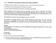
It is the Low-distortion Generator Option, I can't see different versions
of the module for different versions of the UPD.
however 1030.7500.05 might say something completely different.
But if they are not compatible, think of the night mare R&S would
face trying to maintain them.
Here is what I have from one of my .02 manuals.
Attachments

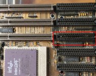
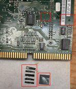
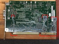
Also be on the look out for this stuff.
Here is the series of pics.
It's still in the mother board,
that card and it migrated to another card as well.
I got about half of it out of mother board with Lacquer Thinner.
Hope this helps.
Here is the series of pics.
It's still in the mother board,
that card and it migrated to another card as well.
I got about half of it out of mother board with Lacquer Thinner.
Hope this helps.
Attachments
-
 02.02 Mutha board Slot3 SludgeDroppings.jpg448.7 KB · Views: 118
 -
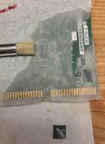 02.01 rear Slot3 Zz Cleaning.jpg319.3 KB · Views: 118
 -
 02.01 rear Slot3 Z GreySludge.jpg403.7 KB · Views: 115
 -
 02.01 rear Slot3 Y removedTags.jpg336.4 KB · Views: 114
 -
 02.01 rear Slot3 X removed 2 Tags.jpg755.8 KB · Views: 119
 -
 02.01 rear Slot3 W removed tab1.jpg426.7 KB · Views: 133
 -
 02.01 rear Slot3 V GreySludge.jpg416.8 KB · Views: 136
 -
 02.01 Front Slot3 U GreySludge.jpg354.4 KB · Views: 146
Last edited:
I scrubbed them last week with IPA.
Digital boards, motherboard, IEC Board, VGA board.
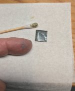
Those are the silicone spacers. Tested and they appear not conductive, even melted.
However when mixed with dust...
Digital boards, motherboard, IEC Board, VGA board.
Those are the silicone spacers. Tested and they appear not conductive, even melted.
However when mixed with dust...
Last edited:

So the R&S analog boards reside in CPU motherboard card slots??!!
If so, I'm impressed that the instrument achieves good performance in that noisey environment! I'd assumed the analog cards had their own separate card cage/motherboard.
If so, I'm impressed that the instrument achieves good performance in that noisey environment! I'd assumed the analog cards had their own separate card cage/motherboard.
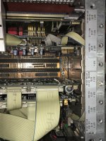
Here are some pics that show how it's configured:
The first pic shows the analog boards, encased,
then enclosed in a separate cage.
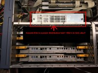
The second pic shows the power distribution hub as I called it. Along the cage that separates the analog from digital. Not the arrow points to this hub and above it is the Mutha' board and the digital cards.
The third pic shows the digital boards in the Mutha board. This is the way you
would find them looking into the UPD from above.
Hope that helps.
Cheers,
The first pic shows the analog boards, encased,
then enclosed in a separate cage.
The second pic shows the power distribution hub as I called it. Along the cage that separates the analog from digital. Not the arrow points to this hub and above it is the Mutha' board and the digital cards.
The third pic shows the digital boards in the Mutha board. This is the way you
would find them looking into the UPD from above.
Hope that helps.
Cheers,
Attachments

Here is information from jeanlucdemarc.
He sent me some of his hand written notes.
Perhaps I already posted the -1 UPD power supply measurements
or not. I included both sets of information here.
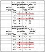
I also need to go back and find 1audio's highlighting
which showed his concern that I needed to take a second
look at them.
Perhaps this might help electronic.
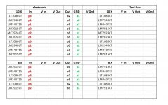
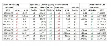
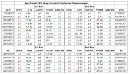
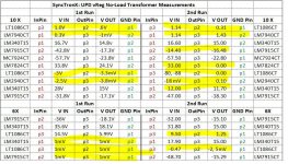
If you don't mind Electonic, if you would humor jeanlucdemark, BSST, and me by taking the vReg measurements from the analog power supply? Its the one with 10X vRegs on one heat sink, 6X vRegs on the smaller heat sink,
and after you disconnect all the boards from it.
Both jeanlucdemarc and I have voltages for them. A third set would go
a long way in helping us understand what they should be? jeanlucdemarc
is there in the EU (EU Power) and has a fully optioned out UPD!
Is your UPD fully optioned out also?
What options that you know of that you may be lacking?
Measure either before or after you take pics.
I will ask him to help us understand it as I'm not sure how
the second pdf, -2 R&S Tests JeanLucdeMarc were made.
This will be good information for anyone having a UPD.
The data follows:
I'll also include a blank form and send you the spread sheet.
So you don't have to reinvent the wheel.
Blank form the last on the right.
Cheers,
He sent me some of his hand written notes.
Perhaps I already posted the -1 UPD power supply measurements
or not. I included both sets of information here.
I also need to go back and find 1audio's highlighting
which showed his concern that I needed to take a second
look at them.
Perhaps this might help electronic.
If you don't mind Electonic, if you would humor jeanlucdemark, BSST, and me by taking the vReg measurements from the analog power supply? Its the one with 10X vRegs on one heat sink, 6X vRegs on the smaller heat sink,
and after you disconnect all the boards from it.
Both jeanlucdemarc and I have voltages for them. A third set would go
a long way in helping us understand what they should be? jeanlucdemarc
is there in the EU (EU Power) and has a fully optioned out UPD!
Is your UPD fully optioned out also?
What options that you know of that you may be lacking?
Measure either before or after you take pics.
I will ask him to help us understand it as I'm not sure how
the second pdf, -2 R&S Tests JeanLucdeMarc were made.
This will be good information for anyone having a UPD.
The data follows:
I'll also include a blank form and send you the spread sheet.
So you don't have to reinvent the wheel.
Blank form the last on the right.
Cheers,
Attachments
-
06.01 -5 UPD Power Supply.pdf174.2 KB · Views: 140
-
 06.01 -4 electonics Measurement.JPG149.2 KB · Views: 92
 -
 05.06 10VdcBulkCap.JPG131 KB · Views: 104
 -
 04.07 SyncNoLoad-Load vRegMeasure.JPG189.4 KB · Views: 103
 -
 04.05 XfrmrCableBoard.JPG162.8 KB · Views: 200
 -
 06.01 -3 Demian Highlighs.jpg199.1 KB · Views: 215
 -
06.01 -2 R&S Tests JeanLucdeMarc.pdf251.9 KB · Views: 103
-
06.01 -1 UPD -2 Power Supply.pdf182.4 KB · Views: 140
@Steve,
In the mean time, I'm still working on my little girls receiver.
parts issues, trying to get everything going etc.
It shouldn't take this long but it does with life and all the
other stuff.
@ electronic, please post your pic of your project or can you please
take some power supply measurements, it will help everyone.
or
what did you find out about the German guy who has schematics
and manuals for sale? We do have 5 or 6 people who are willing
to pitch in and share the burden with you.
Oh I think he mentioned this is bad time right not
many vacations, partying not working, etc happening so it is delayed.
We are patient, no worries.
Cheers,
Last edited:
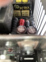
Took down the switcher today, input capacitors failed, luckily they vented OK. Still no schematics.
A replacement OEM unit is however >$500 US, if not discontinued.
A replacement OEM unit is however >$500 US, if not discontinued.
Wondering if the same PSU is used in 05 Variants with newer 486 motherboards.
Best option is to find a newer replacement with -5/-12V @1A, 12V @ 5A and 5V @ 20A and fit it in the same case.
Best option is to find a newer replacement with -5/-12V @1A, 12V @ 5A and 5V @ 20A and fit it in the same case.
Confirmed.
Same PSU in .02 Variant (93 built) and .05 Variant (99 built).
My suggestion to all using the UPD actively is to stop and have the switching PSU serviced.
It is using those nasty RIFA capacitors in certain areas and they do show signs of premature failure.
To remove the PSU in .02 MOD, you have to strip the entire analyzer apart.
In .05 they revised the mounting.
Attachments

Thinking of running the switcher externally.
Some components tend to be hot >80 Celsius as it is a flyback design.
Or design a new and improved switcher to fit inside the case
Some components tend to be hot >80 Celsius as it is a flyback design.
Or design a new and improved switcher to fit inside the case
Last edited:
- Home
- Design & Build
- Equipment & Tools
- Rohde & Schwarz UPD: Troubleshoot then Restore to Glory