I finally purchased a UPL... went with the UPL66 as I was able to get one for about 1/3-1/4 the cost of a regular UPL. Sadly it doesn't have option B1 but I still have my Victor 1khz oscillator and my VP-7725D analyzer if I need to test ultra low distortion. I'm extremely excited to get this and interface it with my SML-01/B5 using their FM tuner performance testing software. I will need to read thru the rest of this thread now so I can get a good idea of what mods/maintenance/upgrades I should perform (such as replacing the HDD with something more reliable). thanks for all the info.
Hi Jok3r7,Hi simingx
,Could you please share the manufacturing files and debugging methods and BOM of the digital IO board? Or where can I buy these things? Thanks
The BOM was pretty much following the component list in the service manual, which also means all the obsolete parts to be sourced from questionable sources over the Internet 🙂
I may still have some spare boards lying around, drop me a PM and I'll sell one to you if I manage to find them...
Hi all,
I've been using the UPL66 for a few days but today when I came home from work and turned it on not much happened. The fans spun up and the power light came on but I didn't hear the standard floppy drive sound during the boot process etc, and no output at all from the VGA connector. I've checked over the PC motherboard and it looks ok, no bulging caps etc. I'm going to start going through the service manual, to check the power supply etc, but I wanted to post here incase anyone had any suggestions in the meantime.
I've been using the UPL66 for a few days but today when I came home from work and turned it on not much happened. The fans spun up and the power light came on but I didn't hear the standard floppy drive sound during the boot process etc, and no output at all from the VGA connector. I've checked over the PC motherboard and it looks ok, no bulging caps etc. I'm going to start going through the service manual, to check the power supply etc, but I wanted to post here incase anyone had any suggestions in the meantime.

Thanks, I'll check that, I assume you're referring to the one on the power supply module. I did do some additional tests since I made my post. It appears that the voltages are correct at the main header coming off of the power supply onto the main digital board. I checked the voltages on the AT power connector (even tho the mobo is getting powered thru the ISA slot) going to the PC mainboard and they also seem OK - although it appears R&S is feeding the board -15V where the AT power supply standard looks to be -12v, but I assume that's no problem for the regulators on the board.
My hope is that the issue is with the PC motherboard itself. It appears to be a Shuttle HOT-555A v3.0. It does not appear to have any bulging/leaking caps. It has an AMD K5 PR133 processor, 8MB ram (2x 4mb Simms). I attached a PC speaker to the header on the board and I was getting a beep --- beep --- beep (continuous). I did try reseating the SIMMS, booting with only 1 SIMM installed, reseating the CPU, etc - no luck. I also tried powering the board up directly on the bench, but unfortunately don't have the proper video card on hand to test with. I can't reproduce the beeping all the time which to me is strange (in the unit or on the bench)
I found someone selling a HOT-555a v3.2 mobo, bought some EDO Simms and a Pentium 166 MMX CPU, as well as a video card to test with. I hope that if I can get the PC motherboard working on the bench, displaying the POST on the monitor with a PCI video card, chances are good the UPL will work again.
I sure hope the main digital board that contains the video card, ide/floppy controller, serial ports, gpib etc isn't causing the problem, since there's no chance I'll find a spare of that. I guess we'll find out.
The seller did advertise this as working, but did a very poor job at packing it (no packing material other than extra cardboard and empty plastic bags stuck inside) so maybe something got finished off on the trip from Belgium to New York. The only thing I did when I got it was change the power selector to 120v from 240. I left the smaller 2.5a fuses in the power inlet connector for now as I don't have 4a on hand, but they did not blow so that's not related to the problem. Unfortunately it did work for 2 days after I got it, so I think I'd have a hard time getting a return...
Last edited:
Strange, as far as I know the UPL only came with either an AI5VG+ or a Kontron motherboard on a custom interposer board. Hopefully it's just the motherboard, I think the mainboards are quite robust.
Interesting, in that case here’s some pics for the record. This is a UPL66, maybe they used different boards in them, shrug.
(Yeah, the battery's missing at the moment since I was playing around with clearing the BIOS, etc, as a last ditch effort)


This motherboard has some atrocious looking early lead free solder joints on the capacitors as well. Fingers crossed...
(Yeah, the battery's missing at the moment since I was playing around with clearing the BIOS, etc, as a last ditch effort)
This motherboard has some atrocious looking early lead free solder joints on the capacitors as well. Fingers crossed...
Well let me know how you get along, worst case I could sell you my spare UPL (with the case in not so good a shape) for a good price since I really don’t have need for 2 of them… 🙂
Cool, thanks for the offer. I’ll post updates here for sure.
Eventually I would like to find the parts to add the digital I/o, and maybe even retrofit the whole front panel / lcd from a regular UPL. B1 would be nice too, but I have the vp-7725d for ultra low distortion needs at the moment.
Eventually I would like to find the parts to add the digital I/o, and maybe even retrofit the whole front panel / lcd from a regular UPL. B1 would be nice too, but I have the vp-7725d for ultra low distortion needs at the moment.
Thankfully I got it working again. That was a stressful couple of days. I bought one of those ISA/PCI motherboard analyzer cards (Kingpin CMBA-4)
The old motherboard was just displaying some dashes across the LED's (when powering on the bench). Not sure.
The new motherboard came in today and was displaying some codes but then would go back to BEEP -- BEEP -- BEEP -- BEEP and hang on this code C6C1 code on the analyzer.
As far as I can tell both 4MB SIMMs in the original motherboard are no good. I had a 32MB PC66 SDRAM stick laying around and I was able to get the new motherboard to boot on the bench. Unfortunately you can't use a regular DIMM in the UPL because the position of them on the board causes them to hit the metal shield on the UPL digital board. I found in one of my retro gaming PC's an "OCZ" Pc166 SDRAM (256MB) - it was one of the first SDRAM DIMM's with BGA Chips on it and much lower profile. Part of the PCB hits the metal shield a little bit but I was able to install the board all the way.
It boots!! It only detects 64MB of RAM from that 256MB stick but that's ok. I have some 8MB EDO SIMM's showing up later in the week, fingers crossed that those work.
The new motherboard appears to have leaky capacitors but it does not seem to have the horrible early lead free solder that the original one did (the joints are nice and shiny) so chances are good I can recap it without any issues.
I'm not super happy about the current root cause, but I'll play around more with the old board/ram/etc when my new test CPU and ram show up later in the week.
Last edited:
Hello Bjirre, I just fixed my UPL today, but the current software version on the machine is 3.0.3, so I would like to ask for detailed steps to update the software to 3.0.6, because I have never used DOS, thank you...UPL Windows 95
Some updates after hours of playing around.
The motherboard i have runs windows 95 very smooth, boot times are fast and i hoped to get the UPL software running on it. I tried the suggestion of Shinja but the UPL software still continued to complain of too less upper memory.
After that i tried running windows 98 but experiences were not that good. graphics were sluggish, long boot times, not that great. Didn't even bother with the UPL software.
Other than getting the UPL working, the network adapter also didn't show up in the device manager and the regular drivers on the internet had no improvement.
Unless somebody has a good clue this trial is done for me.
If everything would run, i still have concerns on the stability, especially because i'm using the B10 option which also requires memory allocations and would make the setup more ciritical.
But i somebody has more experience of information to share I might try it out again in the future.
Cheers,
Bart
@Jok3r7 Good job on fixing the UPL! Welcome to the club!
Installation is quite straight forward, i'll list down here some key steps to follow.
You'll need a keyboard hooked up to the DIN port at the back, without one you'll not be able to enter the commands in DOS.
I've made an older post about the same procedure, Post
Let me know if this works for you, happy to assist further.
Kind Regards,
Bart
Installation is quite straight forward, i'll list down here some key steps to follow.
You'll need a keyboard hooked up to the DIN port at the back, without one you'll not be able to enter the commands in DOS.
- Prepare the floppy disks
- On my drive you'll find the 2 floppy disks required, 1 is for the main firmware, the other is for settings.
- Make sure the floppy's contain the disks and that you can open them in DOS.
- Open the floppy in DOS
- Make sure you are in DOS, you can do this inside the UPL software by pressing the system button, this will exit the UPL program and return to DOS. Alternatively you can press CTRL+F9 combination on your keyboard
- Inside DOS, insert the floppy and type A: this should access the floppy, you'll also see the drive change from C: to A:
- You can run a dir command to see the contents of the floppy
- Run the installation
- The installation of the main firmware floppy (DISK1) is to run UPLINST, type this command while in A: and press enter
- The installation should start
- Run the Settings installation
- Once finished, exchange the floppy disks
- Ensure you're still accessing A:
- Then run SETINST
- Restart UPL
- Once finished, the UPL should restart and show the latest software version.
I've made an older post about the same procedure, Post
Let me know if this works for you, happy to assist further.
Kind Regards,
Bart
Nicely Done!Thankfully I got it working again. That was a stressful couple of days. I bought one of those ISA/PCI motherboard analyzer cards (Kingpin CMBA-4)
The old motherboard was just displaying some dashes across the LED's (when powering on the bench). Not sure.
The new motherboard came in today and was displaying some codes but then would go back to BEEP -- BEEP -- BEEP -- BEEP and hang on this code C6C1 code on the analyzer.
As far as I can tell both 4MB SIMMs in the original motherboard are no good. I had a 32MB PC66 SDRAM stick laying around and I was able to get the new motherboard to boot on the bench. Unfortunately you can't use a regular DIMM in the UPL because the position of them on the board causes them to hit the metal shield on the UPL digital board. I found in one of my retro gaming PC's an "OCZ" Pc166 SDRAM (256MB) - it was one of the first SDRAM DIMM's with BGA Chips on it and much lower profile. Part of the PCB hits the metal shield a little bit but I was able to install the board all the way.
It boots!! It only detects 64MB of RAM from that 256MB stick but that's ok. I have some 8MB EDO SIMM's showing up later in the week, fingers crossed that those work.
The new motherboard appears to have leaky capacitors but it does not seem to have the horrible early lead free solder that the original one did (the joints are nice and shiny) so chances are good I can recap it without any issues.
I'm not super happy about the current root cause, but I'll play around more with the old board/ram/etc when my new test CPU and ram show up later in the week.
Thank you very much Bjirre, but I found a new problem in UPL. When the output level is above about 3.5V, the THD+N of channel 2 is different from that of channel 1. When it is below 3.5V, the values displayed by the two channels are the same. After many attempts, I found that it should be the problem of analyzing channel 2, so I would like to ask if this is normal?@Jok3r7 Good job on fixing the UPL! Welcome to the club!
Installation is quite straight forward, i'll list down here some key steps to follow.
You'll need a keyboard hooked up to the DIN port at the back, without one you'll not be able to enter the commands in DOS.
The is mainly it, keep in mind that this might erase your keyboard regional settings, you can quickly set this back by running the KEYB command in DOS. e.g., KEYB US (for qwerty) KEYB FR (azerty) etc.
- Prepare the floppy disks
- On my drive you'll find the 2 floppy disks required, 1 is for the main firmware, the other is for settings.
- Make sure the floppy's contain the disks and that you can open them in DOS.
- Open the floppy in DOS
- Make sure you are in DOS, you can do this inside the UPL software by pressing the system button, this will exit the UPL program and return to DOS. Alternatively you can press CTRL+F9 combination on your keyboard
- Inside DOS, insert the floppy and type A: this should access the floppy, you'll also see the drive change from C: to A:
- You can run a dir command to see the contents of the floppy
- Run the installation
- The installation of the main firmware floppy (DISK1) is to run UPLINST, type this command while in A: and press enter
- The installation should start
- Run the Settings installation
- Once finished, exchange the floppy disks
- Ensure you're still accessing A:
- Then run SETINST
- Restart UPL
- Once finished, the UPL should restart and show the latest software version.
I've made an older post about the same procedure, Post
Let me know if this works for you, happy to assist further.
Kind Regards,
Bart
@Jok3r7 Good job on fixing the UPL! Welcome to the club!
Installation is quite straight forward, i'll list down here some key steps to follow.
You'll need a keyboard hooked up to the DIN port at the back, without one you'll not be able to enter the commands in DOS.
The is mainly it, keep in mind that this might erase your keyboard regional settings, you can quickly set this back by running the KEYB command in DOS. e.g., KEYB US (for qwerty) KEYB FR (azerty) etc.
- Prepare the floppy disks
- On my drive you'll find the 2 floppy disks required, 1 is for the main firmware, the other is for settings.
- Make sure the floppy's contain the disks and that you can open them in DOS.
- Open the floppy in DOS
- Make sure you are in DOS, you can do this inside the UPL software by pressing the system button, this will exit the UPL program and return to DOS. Alternatively you can press CTRL+F9 combination on your keyboard
- Inside DOS, insert the floppy and type A: this should access the floppy, you'll also see the drive change from C: to A:
- You can run a dir command to see the contents of the floppy
- Run the installation
- The installation of the main firmware floppy (DISK1) is to run UPLINST, type this command while in A: and press enter
- The installation should start
- Run the Settings installation
- Once finished, exchange the floppy disks
- Ensure you're still accessing A:
- Then run SETINST
- Restart UPL
- Once finished, the UPL should restart and show the latest software version.
I've made an older post about the same procedure, Post
Let me know if this works for you, happy to assist further.
Kind Regards,
Bart
Attachments

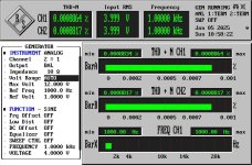
Thank you very much Bjirre, but I found a new problem in UPL. When the output level is above about 3.5V, the THD+N of channel 2 is different from that of channel 1. When it is below 3.5V, the values displayed by the two channels are the same. After many attempts, I found that it should be the problem of analyzing channel 2, so I would like to ask if this is normal?
Please find the measurements on my analyzer, it indeed does not seem right on your analyzer.
Have you ran the selftest? That's where i would start.
- Ensure you have the B10 module installed
- if not, send me a private message with your serial number (or picture of the label on the back) and i'll generate all your license keys.
- If installed, go to options and execute macro
- go to C: - UPL - USER and select SELFTEST.BAS
- Follow the instructions
- Type Ctrl-D on your keyboard to enable the measurement screen at the top of your display.
- Hit F3 to go back to the BASIC environment to see the output of the selftest script (since the output goes away quick)
Kind Regards,
Bart
Attachments
Hi Bjirre, I did SELFTEST twice according to your method, and the results were different. Where should I start checking next?Nicely Done!
@Jok3r7 I've added 2 txt files that show the program source code, the other is the test report (you can find this after the selftest program ran on c: UPL USER.
Off the top of my head here are some suggestions to further dig into:
Kind Regards,
Bart
Off the top of my head here are some suggestions to further dig into:
- Measure externally with another THD analyzer (if possible), figure out if this is coming from the Generator or Analyzer section
- Alternatively insert external voltage into your THD, and focus on the analyzer section.
- Figure out from which voltage this pattern occurs, from that information you can look into the schematics if you can find an amplifier section / attenuator section related to your voltage.
- ...
Kind Regards,
Bart
Attachments
- Home
- Design & Build
- Equipment & Tools
- Rohde Schwarz R&S UPL Audio Analyzer Renovation