UPZ Audio Switcher - DIY version
A bit off topic but still related.
I recently scored a 19" speaker switcher with the sole purpose of reusing the nicely machined case which fits XLR D-series perfectly. The though of making my own UPZ switcher wasn't new for me but now was the time to bite into it!
I started with trying to find out how the communication works from within the UPL to the UPZ. At work we have some UPZ switchers so I used a rs232 sniffer to learn a bit more how the communication works.
Basically when you switch on the option in the UPL the analyzer will send out 16 identity queries for each switcher type.
e.g. a0i*idn?<NL>
This means that a total of 16 input switchers AND 16 output switchers could be daisy chained together and controller from the UPL. Pretty wild!
In the switcher you have to set an ID. Based on this ID the switcher will respond with Rohde & Schwarz, UPZ, <x>, <y> where x is the firmware version and y is the hardware version.
From then on it's pretty simple. The UPL knows who responded and will only allow control for those channels. Otherwise you'll have error messages.
For each channel the UPL will send something like this.
e.g. ia5<NL> which means switching input 5 to bus a.
I set out to make an input and output switcher in one. The output switcher would control phantom power on a bus. The input switcher would work as R&S intended it to be.
The only limitation in my design is that the Arduino I'm using is to slow to respond to 2 queries (input and output query) for address 0 on 1 UART line. The fix is quite simple. I simply set the output switcher to ID 1. I have foreseen dip switches for addressing so I can always change if I want.
I designed PCB's that would fit in my case and added all the components.
Everything came out pretty nice, I used bicolor LEDs everywhere for BUS indication or phantom power indication. For all IO's I used IO expanders from microchip. The brains is an Arduino micro to keep things simple.
IMG_3132.HEIC - Google Drive
All info can be found in my Github if you're interested in making your own version.
GitHub - bvksound/UPZ_Switcher: UPZ Switcher for UPL with Phantom
Pictures/video's and other documentation can be found as always on my drive:
UPZ Switcher - Google Drive
Cheers, Bart
UPL Keyboard Rev3 - Third times the charm!
Who here cannot get enough of keyboards... Anyone?
Ok, I'll start then...
Rev2 of the keyboard worked pretty well but there were some things still bugging me.
A member of the forum pointed me to the original FFC (flat flex cable) connector that fits the digital board. From there the idea started to grow pretty quick of using such a connector on the keyboard and use a standard 34-pin FFC cable. With that idea the digital board could become original again.
Thanks again for the tip! You know who you are! 🙂
The FFC connector is this one. Unfortunately you can only source it from Mouser as far as I see for Europe.
FFC Connector Mouser.
Finding a suitable cable was another story. The mix of the number pins together with the pitch seemed quite rare. But aliexpress to the rescue, plus it's cheap but with a long leadtime and you need a free suez canal!
5 PCS FPC Platte Flexibele Kabel FFC Jumper Pitch 1.25mm Afstand 34 Pin Dezelfde Contact Kant isotropie Type EEN 100 200 300mm Tin Plated|Connectoren| - AliExpress
I reworked my design with cheaper but equal quality buttons and ordered new PCB's from JLCPCB. The design worked great and the FFC cable can be nicely routed inside the analyzer without sharp angles or bends.
IMG_3141.HEIC - Google Drive
IMG_3171.HEIC - Google Drive
The design also removes the need of modifying the LCD housing to make it fit. See mistake of rev2....
Pictures of the build process can be found here:
Rev3_2021 - Google Drive
The design with CAD/BOM/GERBER and Kicad designs can be found on my GitHub:
https://github.com/bvksound/UPL_AudioAnalyzer
One tip I want to share here is to use spacers between the PCB and the mounting holes of the frame. If not you'll easily overtighten the screw and the buttons will be pressed in all the time. I found that TO-220 transistor spacers for heatsinks work quite nicely.
Once the Keyboard and LCD assembly was finished it was finally time to tackle the Digital board. I carefully desoldered all pins and cleaned up the PCB before soldering the FFC connector in place.
https://drive.google.com/file/d/1Sz0jLhVPNNhQ3NxNZygH2JzyrVqxEiNF/view?usp=sharing
The unit is now finished and it makes me sleep at night knowing that everything is back to original. Furthermore it works great off course.
This now means that Rev3 is a drop in replacement for the UPL keyboards!
I have some PCB's available. Send me a PM if interested.
Cheers, Bart
Who here cannot get enough of keyboards... Anyone?
Ok, I'll start then...
Rev2 of the keyboard worked pretty well but there were some things still bugging me.
- Switch choice
The switches I chose are a bit too big and too strong. Furthermore the price shot up and 1 switch is counting up to almost 1 euro. The keyboard holds 44 so it starts to add up. - Connector
In 2013 my young me decided to remove the flat cable connector on the digital board so he could interface with standard pins. I would like to go back to the original state.
A member of the forum pointed me to the original FFC (flat flex cable) connector that fits the digital board. From there the idea started to grow pretty quick of using such a connector on the keyboard and use a standard 34-pin FFC cable. With that idea the digital board could become original again.
Thanks again for the tip! You know who you are! 🙂
The FFC connector is this one. Unfortunately you can only source it from Mouser as far as I see for Europe.
FFC Connector Mouser.
Finding a suitable cable was another story. The mix of the number pins together with the pitch seemed quite rare. But aliexpress to the rescue, plus it's cheap but with a long leadtime and you need a free suez canal!
5 PCS FPC Platte Flexibele Kabel FFC Jumper Pitch 1.25mm Afstand 34 Pin Dezelfde Contact Kant isotropie Type EEN 100 200 300mm Tin Plated|Connectoren| - AliExpress
I reworked my design with cheaper but equal quality buttons and ordered new PCB's from JLCPCB. The design worked great and the FFC cable can be nicely routed inside the analyzer without sharp angles or bends.
IMG_3141.HEIC - Google Drive
IMG_3171.HEIC - Google Drive
The design also removes the need of modifying the LCD housing to make it fit. See mistake of rev2....
Pictures of the build process can be found here:
Rev3_2021 - Google Drive
The design with CAD/BOM/GERBER and Kicad designs can be found on my GitHub:
https://github.com/bvksound/UPL_AudioAnalyzer
One tip I want to share here is to use spacers between the PCB and the mounting holes of the frame. If not you'll easily overtighten the screw and the buttons will be pressed in all the time. I found that TO-220 transistor spacers for heatsinks work quite nicely.
Once the Keyboard and LCD assembly was finished it was finally time to tackle the Digital board. I carefully desoldered all pins and cleaned up the PCB before soldering the FFC connector in place.
https://drive.google.com/file/d/1Sz0jLhVPNNhQ3NxNZygH2JzyrVqxEiNF/view?usp=sharing
The unit is now finished and it makes me sleep at night knowing that everything is back to original. Furthermore it works great off course.
This now means that Rev3 is a drop in replacement for the UPL keyboards!
I have some PCB's available. Send me a PM if interested.
Cheers, Bart
Last edited:
First of all I would like to thank for this thread, especially Bart for the job done and the sharing, this is simply amazing and motivated me a lot to buy one UPL.
I found one in a refurbished equipment shop in Taiwan with options B4, B6, B9, B10.
I was a bit worry when trying it at home as one channel was showing weird measurements, so I disassembled everything, made a deep cleaning and found out that my XLR on the analyzers were having very dry solder joints and broken with an average contact. Few soldering later the UPL was working perfectly on the 2 channels. I took the opportunity to change both fans and on the way to replace the HDD by a CF card, thanks again Bart for the tutorial here.
So this is to give some hints on my side, if the input signal is not stable or fluctuating, this is maybe one direction to look at with the age of those equipments.
Then I was looking as well for the B1 option and without finding it I was starting to look at the schematics to clone it when I found another UPL on eBay broken, to buy for parts with the B1 option. It was a bit of gambling here but I negociated a low price and took the risk.
Happy to find when he reached my place that the only broken thing was the 5V fuse likely due to a misconfiguration of the PC motherboard jumpers as everything was wrong here.
Setting right the motherboard and changing the fuse I got another fully functional UPL.
My question here is regarding this fuse. I read that this area is dissipating a lot of heat and I am wondering if the fuse is properly dimensioned as it is the heating source.
The first UPL have a 8A fuse while the second one had a 6.3A, is there any reason for this?
Is it because not all UPL have the same computer / different consumption and then different fuses?
The schematics seems to tell that 6.3A is the right value.
Just to know if some of you have 8A.
Another question is how do you identify the age of the UPL? I cannot find where to read the date.
Last, does anyone have the B5 option schematics? I am thinking to clone this one.
Thanks.
The DSP - Digital motherboard, has an date mark behind the fron panel.
Circled, with a 2 digit date.
Circled, with a 2 digit date.
Found it. Thanks for your help !
If someone knows about the fuse or the B5 schematics, please let me know.
If someone knows about the fuse or the B5 schematics, please let me know.
First of all I would like to thank for this thread, especially Bart for the job done and the sharing, this is simply amazing and motivated me a lot to buy one UPL.
I found one in a refurbished equipment shop in Taiwan with options B4, B6, B9, B10.
I was a bit worry when trying it at home as one channel was showing weird measurements, so I disassembled everything, made a deep cleaning and found out that my XLR on the analyzers were having very dry solder joints and broken with an average contact. Few soldering later the UPL was working perfectly on the 2 channels. I took the opportunity to change both fans and on the way to replace the HDD by a CF card, thanks again Bart for the tutorial here.
So this is to give some hints on my side, if the input signal is not stable or fluctuating, this is maybe one direction to look at with the age of those equipments.
Then I was looking as well for the B1 option and without finding it I was starting to look at the schematics to clone it when I found another UPL on eBay broken, to buy for parts with the B1 option. It was a bit of gambling here but I negociated a low price and took the risk.
Happy to find when he reached my place that the only broken thing was the 5V fuse likely due to a misconfiguration of the PC motherboard jumpers as everything was wrong here.
Setting right the motherboard and changing the fuse I got another fully functional UPL.
My question here is regarding this fuse. I read that this area is dissipating a lot of heat and I am wondering if the fuse is properly dimensioned as it is the heating source.
The first UPL have a 8A fuse while the second one had a 6.3A, is there any reason for this?
Is it because not all UPL have the same computer / different consumption and then different fuses?
The schematics seems to tell that 6.3A is the right value.
Just to know if some of you have 8A.
Another question is how do you identify the age of the UPL? I cannot find where to read the date.
Last, does anyone have the B5 option schematics? I am thinking to clone this one.
Thanks.
Thanks for your kind words! Happy to help out! Nice scores and repairs btw!
I've added some more pictures of a spare Power supply I have showing the fuses in detail.
Additionally the B5 option schematic is not in the service manual, only the part list is there. I have taken some detailed pictures of mine as a starting point. But having a schematic would definitely be interesting!
B5-Audio Monitor - Google Drive
Power Supply - Google Drive
All the best!
Bart
Thanks a lot for the details and nice photos ! 🙂
It seems that the PCB for the option B5 is dual layer only, do you confirm?
It seems that the PCB for the option B5 is dual layer only, do you confirm?
Last edited:
Thanks a lot for the details and nice photos ! 🙂
It seems that the PCB for the option B5 is dual layer only, do you confirm?
The PCB indeed seems like a 2-layer board.
I disassembled the PCB assembly and took some more photos for your reference.
Cheers,
Bart
Thanks a lot Bart, this is very nice.
Let me know when the new photos are available.
Done, they are the same folder as before on the drive.
Regards,
Bart
Thanks to all, this thread is a fantastic resource.
I have a UPL and am looking to do the standard maintanance on it, bought a CF card and adaptor plus all the relevant cables and adapters in order to change the original year 2000 Fujitsu HD to the flash solution.
I wanted to start off by just putting the cal files onto a floppy and then onto my main WIN10 computer for peace of mind before I get started on it all.
Unfortunately, I post date MS DOS by a little while (first computer at home was a Win95 machine) so am getting my first taste of it all with the UPL system.
I'm just wondering, where do I actually enter the prompts? Exiting into DOS leaves me unable to go any further up the directories than C:\UPL\USER> and I also haven't been able to get any response within the R&S Basic section of the UPL software.
Any help would be appreciated!
Thanks -MSNC
Oh, one thing I recommend doing before any mod is to save the cal files.
Easiest way is via the Floppy drive already in the unit, a 1.44MB is more than enough.
Scandisk / format first the diskette, to be sure you have a usable media.
There are 10 .cal files.
In DOS prompt,
Code:cd C:\UPL\REF copy *.cal A: /v
and that is all. You can do 2 - 3 backups onto several diskettes just to be sure.
Ok, Got this figured out. My Keyboard was set to something other than US layout and so I wasn't able to get access the backslash as it wasn't mapped properly.
IN DOS:
keyb us
Then the above command work perfectly. All cal files are now backed up and I can sleep properly.
IN DOS:
keyb us
Then the above command work perfectly. All cal files are now backed up and I can sleep properly.
Let me add a quick modification I did on my side too.
I was really worried about this heating area just behind the 6.3A fuse on the PSU that apparently all the UPL have (my 2 UPL have the same heating problem here).
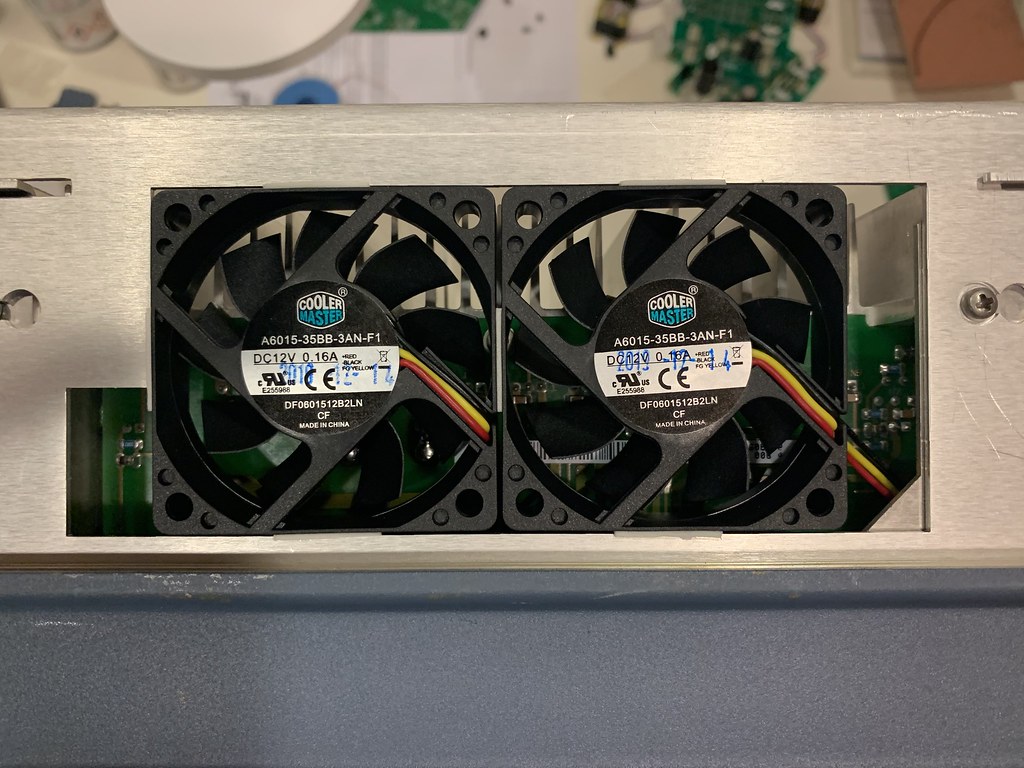
I realized that the large opening in the chassis is exactly compatible with 60mm fans and that there are holes on the top cover to allow air to pass through.
So I went to the computer market and bought 2 fans that I quickly mounted there, extracting the air from the UPL, pulling out the hot air as well from the main PSU heatsink.
It works very well and putting a thermometer on the PCB right in the middle of the fuse I can reduce the temperature by close to 20 degree.
For those who are interested to do the same, might extend the lifetime of those nice equipment.
I will make a nice aluminum plate to mount everything properly, right now I am just using thick double sided tape but it does the job very well too 🙂

I was really worried about this heating area just behind the 6.3A fuse on the PSU that apparently all the UPL have (my 2 UPL have the same heating problem here).
I realized that the large opening in the chassis is exactly compatible with 60mm fans and that there are holes on the top cover to allow air to pass through.
So I went to the computer market and bought 2 fans that I quickly mounted there, extracting the air from the UPL, pulling out the hot air as well from the main PSU heatsink.
It works very well and putting a thermometer on the PCB right in the middle of the fuse I can reduce the temperature by close to 20 degree.
For those who are interested to do the same, might extend the lifetime of those nice equipment.
I will make a nice aluminum plate to mount everything properly, right now I am just using thick double sided tape but it does the job very well too 🙂
There is an extra fan mount on the right side of the unit, as you are facing it from the front.
Also, on later revision models the 5V rail fuse is not between the coil, capacitor and regulator.
You did good however. Probably a 60mm fan is enough.
Also, on later revision models the 5V rail fuse is not between the coil, capacitor and regulator.
You did good however. Probably a 60mm fan is enough.
Thanks for your comments.
I am interested to see how the latest PSU are designed especially the fuse part.
Do you have any photo to share?
I am interested to see how the latest PSU are designed especially the fuse part.
Do you have any photo to share?
There is an extra fan mount on the right side of the unit, as you are facing it from the front.
Also, on later revision models the 5V rail fuse is not between the coil, capacitor and regulator.
You did good however. Probably a 60mm fan is enough.
That’s where the speaker monitor option goes, but i agree, excellent hole to re-use if you don’t have that option.
Will do some photos and new thermals this week sometime.
Yes it is for the speaker cutout, but is that option really necessary? Or at least the speaker.
Yes it is for the speaker cutout, but is that option really necessary? Or at least the speaker.
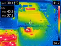
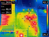
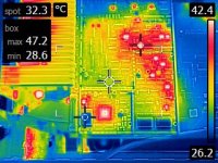
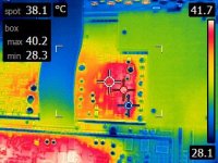
Right, as promised. Newer thermal images
These are looking down at the DSP board.
Please NOTE this is the newest version /w 300MHz board.
One disadvantage of this configuration is the DSP IC getting pretty hot after 10 minutes. On previous revisions with the Pentium CPU, the processor cooler was indirectly cooling this DSP IC as well.
Can be addressed by using an IC and a side vent fan.
----
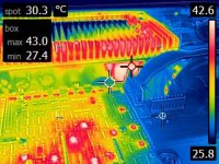
The digital board option I believe it's obsolete, gets pretty hot and draws significat current.
----
Component side of the PSU is marginally hot
Not sure it is worth having it installed.
These are looking down at the DSP board.
Please NOTE this is the newest version /w 300MHz board.
One disadvantage of this configuration is the DSP IC getting pretty hot after 10 minutes. On previous revisions with the Pentium CPU, the processor cooler was indirectly cooling this DSP IC as well.
Can be addressed by using an IC and a side vent fan.
----
The digital board option I believe it's obsolete, gets pretty hot and draws significat current.
----
Component side of the PSU is marginally hot
Not sure it is worth having it installed.
Attachments
Last edited:
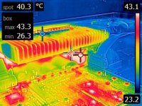
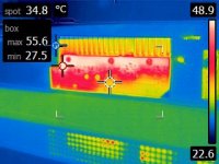
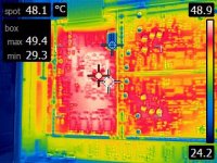
Bottom part, representing the Analog stage (Analyzer) and back side of PSU.
Things get hot here as well.
Things get hot here as well.
Attachments
Last edited:
Thanks for the photos and sorry for my late reply here.
Regarding the overall cooling I am wondering if there is not better solutions nowadays than the original papst 92mm fan at the back of the UPL with a better airflow.
Maybe that will reduce overall the UPL temperature.
I will look at PC fans.
Regarding the overall cooling I am wondering if there is not better solutions nowadays than the original papst 92mm fan at the back of the UPL with a better airflow.
Maybe that will reduce overall the UPL temperature.
I will look at PC fans.
- Home
- Design & Build
- Equipment & Tools
- Rohde Schwarz R&S UPL Audio Analyzer Renovation