That's great Abetir, good to hear your fine efforts are rewarded and you like the sound too.
I would be interested to know what the stability of bias current is with your arrangement.
When you mount the amplifier in a case, could you then measure the mV drop across either
0R22 resistor after say, just turned on then after 20 seconds, 1 min, 5 mins?
You could play music in between measurements if you wish, as long as you play the same music
and volume each time you repeat a test. Then leave it without music for another 5 mins and
take a final measurement - 5 measurements in total.
The reason I ask is to be more certain of the Vbe multiplier (Q9) circuit's thermal coefficient.
It may work fine under some conditions of use but not others, so information like this is helpful
when we change the details of the original design.
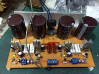
Nice work!Finally my P3A sung loud & clear
After about 2hrs of playing, DC offset settled at 02.4dcmv. AC at the output is dead flat at 00.0v (when no signal applied). Very silent too, no humming issues.
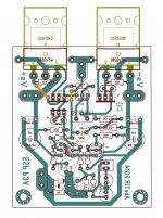
Since my PSU was at +-27vdc, I used BC550C for the input diff. MJE15032/33 for drivers 2SA1209 for VAS and 2SC5200/SA1943 for the output. Everything works well no overheating problem.
The lay-out was a success, I could say, I now possess two wonder amps that display remarkable soundstage for a few parts count. (VSSA & P3A)
Many thanks to Ian Finch, Bigun and AndrewT for their inputs.


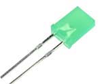
If you have some time put this green led closer to transistor,Use a flatbed led and put in thermal contact these two devices.
Then post this pcb pdf.🙂
Attachments
Last edited:
Hi thimios!
Flatbed led? 🙄 are those the kind of LEDs used by some Elektor projects?
The flat surface of the transistor is tied to the LED. Do they have the same voltage drop as with the standard green LED?
Nice idea!
Flatbed led? 🙄 are those the kind of LEDs used by some Elektor projects?
The flat surface of the transistor is tied to the LED. Do they have the same voltage drop as with the standard green LED?
Nice idea!
Do they have the same voltage drop as with the standard green LED?Hi thimios!
Flatbed led? 🙄 are those the kind of LEDs used by some Elektor projects?
The flat surface of the transistor is tied to the LED. Do they have the same voltage drop as with the standard green LED?
Nice idea!
Great qwestion!
You can measure this(easy way) ,a battery ,a led and one resistor.🙂
the "flat" LEDs are available in many colours.
This gives a range of voltages that can be used for references.
But each manufacturer ends up with different voltage for their colour.
Some reds are as high as green and yellow.
Others can be all over the voltage range.
It gets expensive buying different colours from different manufacturers just to find one that suits the duty.
BTW,
I built the Roender and didn't have any "flat" LEDs for tempco.
I just filed the round to flat and tied them to the adjacent transistors for thermal coupling.
.....I just filed the round to flat and tied them to the adjacent transistors for thermal coupling.

but somehow, I seem to have lots of these unused since the 1970s.
Last edited:
Abetir : I have some rectangular LEDs that would be perfect for the job. Some red and green regular brightness ones. Remind me next time you pass by the house.
Fantom_mayonaise of elab.
Fantom_mayonaise of elab.
Excellent rough512!
I'll give you a ring when I get back in the city, hopefully this coming July. 🙂
Many thanks!
I'll give you a ring when I get back in the city, hopefully this coming July. 🙂
Many thanks!
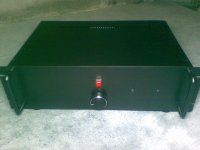
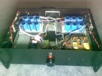
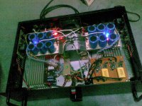
...just wanted to share my P3A in its newfound home..🙂...not so good image shots though...🙁
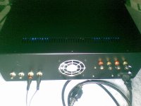
I have included a softstart, dc protect, a fan and an input buffer (courtesy of Dr. Bora Jagodic) I have followed hifisonix's method on "power amp wiring for zero noise problems". It works!
@ Ian Finch, sorry cant' provide you with the voltage measurements yet, i didn't realize that it is going to be impossible to slip the meter probes in my amp board arrangement.
Best regards!
Attachments
Member
Joined 2009
Paid Member
Looks very good !
Don't go blowing up the amp trying to get meter probes in there and then they slip and short something out (done that myself!) - tack on a couple of small temporary wires to the legs of the power transistors that lead out of the chasis (then you can put the lid on the chasis for more accuracy) and clip them onto the meter safely.
Can you post details of your input buffer from Bora ?
Thanks Bigun,
The input buffer was provided to me with confidentiality thru personal request to Dr. Bora. Sorry can't post the schematic but you can email him and send to him the PCB screenshot as a reference as he have a lot of audio designs. He is a very kind person. 😉
The input buffer was provided to me with confidentiality thru personal request to Dr. Bora. Sorry can't post the schematic but you can email him and send to him the PCB screenshot as a reference as he have a lot of audio designs. He is a very kind person. 😉
Member
Joined 2009
Paid Member
The pcb design can be reverse engineered - best have a moderator remove it if you are concerned.
 removed copyrighted material....
^thanks Sir Tony,
....will be very cautious the next time, my mistake.
My apologies to Dr. Bora.
....will be very cautious the next time, my mistake.
My apologies to Dr. Bora.
no worries Abe, you only need to ask permission from the copyright owner, and when he agrees, you can post pictures....😉
Member
Joined 2009
Paid Member
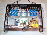
Nicely done RSK. It's a nice amp and won't generate too much heat - which might be important given where you live. The last time I was in Seremban it was rather warm.
Do you have good thermal contact between the Vbe multiplier and one of the driver transistors ?
Do you have good thermal contact between the Vbe multiplier and one of the driver transistors ?
Nicely done RSK. It's a nice amp and won't generate too much heat - which might be important given where you live. The last time I was in Seremban it was rather warm.
Do you have good thermal contact between the Vbe multiplier and one of the driver transistors ?
Hello Bigun,
Vbe multiplier, are you refering to Q9? I followed Rod's layout, it is not in contact with any output. Should I link it with wire soldered or leave as it is?
Yet to test it, but so far it is stable with 1 to 2mV dc offset on both channel.
I live in KL.
- Home
- Amplifiers
- Solid State
- Rod Elliot P3A Layout - Critics