Desolder one other source resistor from an adjacent FET and compare the readings. Other components may be skewing the readings.
k, also i went back and tested all remaining fets, all 28n15 tested fine, all 36p15 gave a negative reading in the 200m ohm range on leftleg center leg, a no reading on left leg right leg, and a good reading on right leg center leg, should i be concerned?(also went and tested the shorted ones and confirmed they r bad.
will let you know what happens with resistors, thanks
will let you know what happens with resistors, thanks
alright thanks, i tested the smd after removing the adjacent .1ohm resistor and got same reading, so i decided to test the smd next the the .1 ohm resistor i just now removed, measured 24 ohms, within tolerance, yet the one adjacent to blown fet still wont read anything but about 37 ohms. does the smd need replacing?
If it's connected to the source resistor at the same point and has the same markings, yes. Order extras.
also should i be worried about the power/input side of the board, or does everything seem okay there to you?
also, i have having some issues finding the resistors 20r0 and 37r4, i checked future, they have 0, is there anywhere else i can check, also check online components.
also, i have having some issues finding the resistors 20r0 and 37r4, i checked future, they have 0, is there anywhere else i can check, also check online components.
Last edited:
also, i have having some issues finding the resistors 20r0 and 37r4, i checked future, they have 0, is there anywhere else i can check, also check online components.
lol, was adding stuff to cart as we speak.
heres what i am looking @ now
http://www.mouser.com/Search/Produc...rtualkey66000000virtualkey660-RK73H1ETTP20R0F
heres what i am looking @ now
http://www.mouser.com/Search/Produc...rtualkey66000000virtualkey660-RK73H1ETTP20R0F
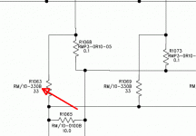
They should be 0805s. Wait until you get the diagram, it will tell you what size they are. There is a suffix on the part number on the schematic diagram. The following show the various sizes:
B = 0805 (0.080" x 0.050")
C = 1206 (0.120" x 0.060")
D = 1210 (0.120" x 0.100")
The image below is an example from a different Rockford amp.
B = 0805 (0.080" x 0.050")
C = 1206 (0.120" x 0.060")
D = 1210 (0.120" x 0.100")
The image below is an example from a different Rockford amp.
Attachments
okay i got my schematics in today, i cannot seem to find the numbers off the pc boards on the schematics. is it possible they are abbreviated? like r59 for r2059? or i am just not looking hard enough? thanks
- Status
- Not open for further replies.
- Home
- General Interest
- Car Audio
- rockford fosgate t15002 amp troubles
