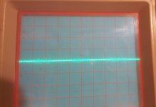
All measurements: 0.1 V/Div 5 uS/Div
Using probe ground on non-bridging speaker terminal as reference.
No treble boost on this amplifier.
Adjusting gain does not change anything.
Low pass and full pass positions do not change anything.
Using probe ground on non-bridging speaker terminal as reference.
No treble boost on this amplifier.
Adjusting gain does not change anything.
Low pass and full pass positions do not change anything.
Attachments
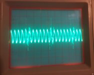
Yes, it flattened out to resemble Ch 4 above then as soon as the P.S. ammeter bumped up it changed to the image below and stayed that way until I cycled the remote.
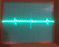
1.05 mV across the resistor in image, after I cycled the remote the voltage across the source resistor read 0.04 mV although the pot was not adjusted.
0.1 V/Div and 5 us/Div
1.05 mV across the resistor in image, after I cycled the remote the voltage across the source resistor read 0.04 mV although the pot was not adjusted.
0.1 V/Div and 5 us/Div
Attachments
It appears that the oscillation is what's causing the increase in current draw and it doesn't stop until the supply is shut down.
Which channels did you replace the output transistors in?
Which channels did you replace the output transistors in?
I didn't do anything to the power amplifier section on this amplifier, other than the two source resistors I replaced last night in Ch 4.
I replaced the power supply FETs and the 2G Transistors Q2 and Q3 in the power supply.
The output FETs may be original, 540s and 9540s, I really couldn't see any evidence that they were changed before.
I did test them initially for shorts when I first got the amplifier.
I replaced the power supply FETs and the 2G Transistors Q2 and Q3 in the power supply.
The output FETs may be original, 540s and 9540s, I really couldn't see any evidence that they were changed before.
I did test them initially for shorts when I first got the amplifier.
Last edited:
They all read a little out of tolerance.
R178: 4.17 ohms
R278: 3.03 ohms
R378: 3.12 ohms
R478: 3.08 ohms
Which component for Pin 1: in post #50?
I will have to get back to it this afternoon when I get back in.
R178: 4.17 ohms
R278: 3.03 ohms
R378: 3.12 ohms
R478: 3.08 ohms
Which component for Pin 1: in post #50?
I will have to get back to it this afternoon when I get back in.
I didn't intentionally post #50.
Do you have a capacitance meter to check the capacitors in series with those resistors?
Do you have a capacitance meter to check the capacitors in series with those resistors?
I have a Fluke 187 that will measure capacitance, but I'm not sure how well in circuit.
I also have, if you squint real hard, you might loosely call an esr meter (MESR-100). It is supposed to test esr in circuit and I have actually identified bad capacitors before in circuit. It also seems to work okay when comparing known good capacitors to other capacitors of the same value that are in question.
I also have, if you squint real hard, you might loosely call an esr meter (MESR-100). It is supposed to test esr in circuit and I have actually identified bad capacitors before in circuit. It also seems to work okay when comparing known good capacitors to other capacitors of the same value that are in question.
They are all smd components so unless the resistor would stand a better chance of resisting damage by removing and re-installing I will just remove the capacitors to test. I guess it's six of one and half a dozen of another.
What do you think?
What do you think?
Whatever works best for you. The resistors are likely more rugged. Heating them and sliding them off of their pads is quick and easy.
With Rx78 removed.
Meter with open probes reads 0.38 nF
C128: 0.086 uF
C228: 0.077 uF
C328: 0.086 uF
C428: 0.079 uF
I did find R278 out of tolerance, reading 4 ohms and should be 2R7 ohms
Meter with open probes reads 0.38 nF
C128: 0.086 uF
C228: 0.077 uF
C328: 0.086 uF
C428: 0.079 uF
I did find R278 out of tolerance, reading 4 ohms and should be 2R7 ohms
Is ch3 still the noisiest?
If so, does the removal of R378 make a difference in the amplitude of the noise?
If so, does the removal of R378 make a difference in the amplitude of the noise?
- Home
- General Interest
- Car Audio
- Rockford Fosgate Power 400a4