If you have 'canned air', invert it and cool the transistor, then try heating it. That will make the bias swing more than just heating. Be aware that the current may increase significantly when the bias transistor is frozen.
Could the induced noise be from a 12v switching power supply on the bench?
Does your signal source have grounded shields?
Could the induced noise be from a 12v switching power supply on the bench?
Does your signal source have grounded shields?
Manipulating temperature of Q407:
Initial idling with position of pot described early by setting bias while using ammeter on power supply.
2.1 mV
Cooled with canned air, rose to 8.1 mV
Allowed to equilibrate, fell to 1.2 mV then rose to settle at 2.19 mV
Heated with hot air, rose to 3.5 mV
Removed heat allowed to come back to room temp, settled at 2.3 mV
If you drive a sine wave into the amp, is there any distortion in ch4 with the pot at the fully CCW bias position?
If you heat the amp up (including the heatsink and outputs, during bench testing), does the bias hold on ch4 from room temperature to near thermal protection?
I remember someone else having the same problem on a 4ch rockford amp so this isn't the firt time this has been a problem.
If you heat the amp up (including the heatsink and outputs, during bench testing), does the bias hold on ch4 from room temperature to near thermal protection?
I remember someone else having the same problem on a 4ch rockford amp so this isn't the firt time this has been a problem.
The top and the bottom of the sine wave is 'fuzzy/wide', attached is the image, 1 kHz sine wave, bias pot full ccw.
To get voltage back to 0.040 mV after turning pot full CCW I had to cycle the remote. It was at 1.8 mV from previous test.
What I also noticed is that with pot full CCW and reset to 0.04 mV , when signal was feed into to get the pic below, the voltage jumped to 6.1 mV, but when the input was removed the voltage dropped to 2.8 mV and stayed there even though pot was still full CCW.
Start of 'bench test' the voltage (across the source resistor) was 2.3 mV. I ran the amp with all 4 channels loaded, music moderately clipped, for 45 minutes. The amplifier never shut down, but the heat sink was so hot you surely would not want to touch it for more than a few seconds. While music was running voltage reached 100 mV + for short bursts of music. As soon as I removed signal and amplifier still hot, voltage was at 9.89 mV. When the amplifier finally cooled the voltage was at 1.8 mV
This may be it, I still have that thread pulled up and was going back to it.
www.diyaudio.com/community/threads/rockford-400a4.362431/
It seems I was reading another one with a similar problem and the individual never came back to follow up on if the issue was ever resolved. I will try and find that one also.
Attachments

Was this the only channel that didn't hold the bias settings at high temperatures?
In that thread, was the same channel causing the problem?
In that thread, was the same channel causing the problem?
I didn't check them, I will have to run the amp again to see.
The other thread is a little confusing.
Post #59 Ch 2 and Ch 4, he describes similar behavior with respect to setting the bias. He says it starts at ~0 and about halfway jumps to 2 mV +, then has to cycle the remote to reset. On my amplifier it is only Ch 4.
Post #63 he says he sets Ch 2 and Ch 4 bias to 1.1 mV, that is not like mine. He never explains what changed to allow him to set them at 1.1 mV.
Post #65 he says heating the bias transistors caused the bias to decrease. On my amplifier heating the transistor caused the voltage to increase.
Post #1 he says that when setting the bias at a certain point the amplifier suddenly draws 'excessive' current (8 + amps), no signal, no load. On my amp the voltage across the source resistor increases suddenly, but the amplifier doesn't draw more than about 2 amps.
Last edited:
I have to remove the board from the heat sink to put the new crossover switch in tomorrow. I will pull one leg of the source resistors out of the circuit then to make sure.
Update:
So, when checking the source resistors in Ch 4, I found one that was fluctuating between 0.3 ohms and 0.2 ohms while one leg pulled (meter 'zero' = 0.2 ohms). I pulled it completely out of the circuit and checked it and it actually read 0.1 ohms which is less than just the probes touching together, so I cant explain that, but I replaced it.
It did change the behavior of the pot in Ch 4 (giving me more control of voltage), but also affected Ch 1,2 and 3 making them more erratic. i.e. turning pots CCW increased voltage once ~ 2 mV was reached. At one point the amplifier was pulling 10 amps at idle and the bias voltages were all over the place channel to channel. I could not get any particular behavior to repeat consistently, so I reset the amp, set all the bias voltage to ~ 1.2 mV while relatively warm and called it a night.
This morning while at room temp the voltages on all channels were 0.7 mV +/- 0.1 mV.
I set them at 1.05 mV +/- 0.03 mV and I am about to test it with music with all channels loaded with dummy loads.
Should the voltages still be at ~ 1.0 mV when the amp is hot?
If they have risen should I set them while they are hot to 1.0 mV? I know there is a mention of this in the tutorial, but I think the wording used was a "significant increase when hot", just making sure what is significant.
I am not sure I fully understand what oscillation means relative to an amplifier. I know what the definition of what oscillation is mechanically, but not 100% sure as used in electrical components and the outcomes. It does appear that when a certain voltage across the source resistors is reached then things go haywire. Being that cycling the remote resets everything, to me it seems that the amplifier is being locked into a particular behavior.
'Significant' would vary by amplifier. I think you'd have to take it on a case by case basis. Virtually no amp will remain exactly the same hot or cold. Post the variation you find.
Oscillation would appear as a widening (vertically) of the waveform. There was some evidence of it on the waveform you posted but that can be due to incorrect biasing. The frequency of oscillation, as well as the amplitude, can determine the amount of current draw for a particular amp. Technically, there should be no oscillation for this class of amp.
For some class D amps, there is enough carrier wave leaking through the output filter to look like there is a problem but that's entirely different than what we're dealing with here.
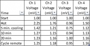
Ran the amp for an hour. Removed signal and took below measurements at various times. After test amplifier idled at 1.2 amps.
After taking voltage readings, I input a 80 Hz sinewave and a 1 kHz sine wave.
80 Hz, oscillation top and bottom on all channels. Greater amplitude than image in #24.
1000 kHz, oscillation similar to image in #24, on Ch 3 and Ch 4. Ch 1 and Ch 2 'sharp' sinewave.
What do you think?
After taking voltage readings, I input a 80 Hz sinewave and a 1 kHz sine wave.
80 Hz, oscillation top and bottom on all channels. Greater amplitude than image in #24.
1000 kHz, oscillation similar to image in #24, on Ch 3 and Ch 4. Ch 1 and Ch 2 'sharp' sinewave.
What do you think?
Attachments
What's the resistance between the input RCA shields and the primary ground (no RCAs plugged in).
Does the signal source have grounded shields?
If you set the amp to low-pass and drive a signal (80Hz) into it, do you still see the oscillation?
In full range, does the oscillation on the output change if you bridge the front/rear shields with a jumper wire?
Does the signal source have grounded shields?
If you set the amp to low-pass and drive a signal (80Hz) into it, do you still see the oscillation?
In full range, does the oscillation on the output change if you bridge the front/rear shields with a jumper wire?
956 Ohms on all channels.
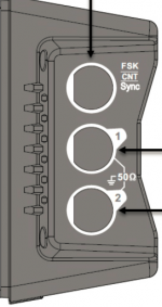
I am not sure. It is a mains powered signal generator. It uses a bnc to rca cable to carry the signal. The plug is two terminal as is the power supply, so I am thinking they are isolated from one another. Is this correct. Attached is what it looks like.
I am not sure. It is a mains powered signal generator. It uses a bnc to rca cable to carry the signal. The plug is two terminal as is the power supply, so I am thinking they are isolated from one another. Is this correct. Attached is what it looks like.
Attachments
You didn't give the make/model so I don't know precisely what you have. Try connecting the ground (should be somewhere in the case of the generator) to the ground of the 12v power supply.
Does the signal source have grounded shields?
If you set the amp to low-pass and drive a signal (80Hz) into it, do you still see the oscillation?
In full range, does the oscillation on the output change if you bridge the front/rear shields with a jumper wire?
Does the signal source have grounded shields?
If you set the amp to low-pass and drive a signal (80Hz) into it, do you still see the oscillation?
In full range, does the oscillation on the output change if you bridge the front/rear shields with a jumper wire?
It is a UNI-T UTG932.
https://www.amazon.com/UNI-T-Generator-Arbitrary-Dual-Channel-Frequency/dp/B08SJNLJCM
I may have misunderstood. When you say in the case, are you saying to open the case? If I disassemble it, I will void the warranty by breaking the warranty seal.
https://www.amazon.com/UNI-T-Generator-Arbitrary-Dual-Channel-Frequency/dp/B08SJNLJCM
I may have misunderstood. When you say in the case, are you saying to open the case? If I disassemble it, I will void the warranty by breaking the warranty seal.
I don't see a ground. The best that you might be able to do is to jump the BNC case to the 12v PS ground.
If you set the amp to low-pass and drive a signal (80Hz) into it, do you still see the oscillation?
If you set the amp to low-pass and drive a signal (80Hz) into it, do you still see the oscillation?
low-pass 80 Hz, I can see it on all channels. When I ground the shield of the generator to the power supply, Ch 1 and 2 it disappears. Ch 3 and 4 it improves by ~ 75 % reduction.
Full pass 80 Hz no difference jumping rca shields.
1 kHz Ch 1 clean, Ch 2 minimum, evident on Ch 3 and 4 about the same as original image #24. Audible humming on all channels, ( not sure if its coming from the transformer or not). When generator grounded to power supply oscillation shifts from top of sine wave to bottom of sine wave or vice versa, depending on which channel. i.e. Ch 3 is opposite of Ch 4.
Is there any sign of oscillation on the output if you remove all signal?
If you set the treble boost to minimum?
Set the gain to minimum?
Low pass, no signal?
If you set the treble boost to minimum?
Set the gain to minimum?
Low pass, no signal?
- Home
- General Interest
- Car Audio
- Rockford Fosgate Power 400a4