There's no point in doing anything with the power supply until you troubleshoot the output stage.
What probe/terminal combination gave you 15.18 ohms on Q10?
If you want to replace the gate resistors and test the supply, desolder and clean the pads for the red/black wires. Do this on the power supply side of the amp.
What probe/terminal combination gave you 15.18 ohms on Q10?
If you want to replace the gate resistors and test the supply, desolder and clean the pads for the red/black wires. Do this on the power supply side of the amp.
So all the output transistors should be near 0 also correct? And the rectifiers? Is there a difference in the transistors on the output side it assortment of 3415 and 6215.
You have to check in all combinations legs...
1-2
1-3
2-3
No. 0 ohms is bad. You need to slow down and read more carefully.
There are lots of differences between the 3415 and 6215 but you do basic testing, while in the circuit, the same way.
1-2
1-3
2-3
No. 0 ohms is bad. You need to slow down and read more carefully.
There are lots of differences between the 3415 and 6215 but you do basic testing, while in the circuit, the same way.
Output side of the board. the gate resistors are not on the board. I removed them to replace them, since the 10 will be ok i am putting them on.
Loc: 1-2 1-3 2-3
Q112 .3 .2 .2
Q111 20.4 20.4 .2
Q110 .2 .3 .3
Q106 20.4 20.4 .1
Q105 1.6 1.5 .3
Q109 14.2 14.8 13.6
Q108 13.8 13.7 2.24
Q107 11.8 13.5 .4
Q103 10.3 13.3 2.0
Q102 10.3 13.7 .4
Q101 11.4 14.0 0
Loc: 1-2 1-3 2-3
Q112 .3 .2 .2
Q111 20.4 20.4 .2
Q110 .2 .3 .3
Q106 20.4 20.4 .1
Q105 1.6 1.5 .3
Q109 14.2 14.8 13.6
Q108 13.8 13.7 2.24
Q107 11.8 13.5 .4
Q103 10.3 13.3 2.0
Q102 10.3 13.7 .4
Q101 11.4 14.0 0
Last edited:
105, 110 and 112 appear shorted. Desolder 2 of the 3 legs on those transistors and confirm that none of the rest of the transistors read near 0 ohms 2-3.
The bottom 6 FETs may be OK. The first set of readings looked like some may be shorted but if they read in the meg-ohm range, they may have survived. Order enough 3415s and 6215s to replace all of the FETs on that side.
Check all of the gate resistors.
With the red/black wires still disconnected, connect a jumper from pin 2-6 on U17. Measure the DC voltage for all output locations red on leg 1, black on 3.
Check all of the gate resistors.
With the red/black wires still disconnected, connect a jumper from pin 2-6 on U17. Measure the DC voltage for all output locations red on leg 1, black on 3.
Ok I ordered the transistors, I replaced all the gate resistors on the PS side of the amplifier. I will desoder the wires today,install a jumper and post the voltage.
A word of caution...
After you power up the supply, the rail caps will be charged to about 110v DC. They will NOT self discharge. You will need to discharge them through a large resistor or some other load. If you don't have anything. A small desk type lamp with a conventional incandescent bulb (not LED or fluorescent) will work. Turn the lamp on and touch the prongs for the plug across the rail cap terminals. The lamp will light brightly for a second, then dim. Confirm that the caps are discharged by reading the DC voltage across them.
After you power up the supply, the rail caps will be charged to about 110v DC. They will NOT self discharge. You will need to discharge them through a large resistor or some other load. If you don't have anything. A small desk type lamp with a conventional incandescent bulb (not LED or fluorescent) will work. Turn the lamp on and touch the prongs for the plug across the rail cap terminals. The lamp will light brightly for a second, then dim. Confirm that the caps are discharged by reading the DC voltage across them.
oh ok i understand thanks, i have removed any of the transistors that were not in the mega range, now the blue resistors are the gate resistors for this side correct? A few of them are out of tolerence. Which resistors do i buy to replace them 15ohm but which wattage? .25, i have 1 watt but they are larger.
The gate resistors connect to the gate leg of the FETs.
Replace them with whatever was used previously.
They are 1/4 watt.
Replace them with whatever was used previously.
They are 1/4 watt.
So I replaced everything and hooked it up with a ten amp fuse it blew the fuse, then the 15 amp worked, powers up no protection light. The audio sounds off to me?
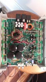
Perry what are the small brown components (FB5) next to the resistors on the output side of the board? One of them is broken at the leg on the board i am troubleshooting with your help. what are they called to order them?
Last edited:
It's a ferrite bead on a piece of wire. Is there any way to solder it back to the board?
In what way does the output sound 'off'?
If you power it up with a 15 amp fuse, then power it up with a 10 amp fuse, does it blow the 10 amp fuse?
In what way does the output sound 'off'?
If you power it up with a 15 amp fuse, then power it up with a 10 amp fuse, does it blow the 10 amp fuse?
It sounded static, or unclear, i was using a 8ohm shelf speaker, it played and stayed on with no protection, and got warm. i switched the a/v jacks, I was using a dvd player for the outputs. Its all i had, unless i soldered a wire. I can check if it blows a 10 amp now. It just sounded off, and pops or crackles when i selected the subsonic filter on or off. Kind of hard to explain.
(Amp 1)
I tried to soder it on the board and the brown diode slid down, i slide it back up and sodered it, but i thought it may fail?
(Amp 1)
I tried to soder it on the board and the brown diode slid down, i slide it back up and sodered it, but i thought it may fail?
- Status
- Not open for further replies.
- Home
- General Interest
- Car Audio
- Rockford Fosgate 1001bd Repair Help