If you replaced the output transistors, the old bias settings are not reliable and could cause the new outputs to overheat and fail. Setting them full CCW sets the bias as low as possible so it isn't a problem during testing.
By 'tutorial', are you referring to the online material?
When you tested the PNP driver, what did you get B-C and B-E?
Yes, you said many times people think they are increasing power output and they end up destroying the amp. Should I turn them down now?
Q2 in circuit was .823V B-C and very close to that B-E. I think it was a little higher even.
Last edited:
I just noticed that R20 I must have lifted the trace off the board when unsoldering. I can't get continuity between it and Q7. I'll have to repair that. It looks like if you take all of the screws out, you could lift the whole board assembly right out of the heatsink? I could maybe fix that broken trace underneath?
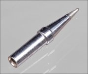
Question about tip life on this iron. How often should I have to change that ETS conical tip? The end is very narrow brand new but, it tapers larger as it wears. It's already quite a bit larger than I would expect. Am I doing something wrong? Too hot maybe?
Question about tip life on this iron. How often should I have to change that ETS conical tip? The end is very narrow brand new but, it tapers larger as it wears. It's already quite a bit larger than I would expect. Am I doing something wrong? Too hot maybe?
Last edited:
Are you saying that you replaced the 3205s and outputs without removing the board from the heatsink?
Can you post a good quality photo of the area around R20 (after cleaning the area with alcohol or acetone and cotton swabs)?
If the tip has changed in any way, it's damaged and will very shortly become unusable. The ETS tip is only for intermittent use (in my opinion). The ETA tips that I generally use will last a year or more with daily use. Reducing the tip temperature from 800 (mine generally stays at the highest temperature when I'm replacing parts) to about 600 will also help increase tip life.
Are you saying that you replaced the 3205s and outputs without removing the board from the heatsink?
Can you post a good quality photo of the area around R20 (after cleaning the area with alcohol or acetone and cotton swabs)?
If the tip has changed in any way, it's damaged and will very shortly become unusable. The ETS tip is only for intermittent use (in my opinion). The ETA tips that I generally use will last a year or more with daily use. Reducing the tip temperature from 800 (mine generally stays at the highest temperature when I'm replacing parts) to about 600 will also help increase tip life.
No, I removed the board when replacing the 3205s. That resistor (R20) had fried originally. I'm not sure if the trace was gone then and I didn't notice or, if it went the second time I removed it to check Q7 again.
I don't know how great the photo quality is. It's certainly not up to your level.
The tip just tapers as it goes to the end. It's now as if the bottom 3/16 has worn away so it's a lot larger than when I started. I guess I need some ETA tips? Also what flux do you use for work like this?
Attachments
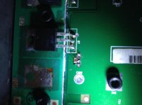
Actually I think I made a mistake. The bottom trace in the picture goes over to Q2. It does still have continuity so it might be ok. The top one in the picture goes to Q7 and does have continuity with Q7. It might still work
So this tip isn't too big for this tiny work in a crammed board?
https://www.amazon.com/Weller-ETA-Screwdriver-PRICE-EACH/dp/B0002BSP3Q
So this tip isn't too big for this tiny work in a crammed board?
https://www.amazon.com/Weller-ETA-Screwdriver-PRICE-EACH/dp/B0002BSP3Q
Last edited:
The ETA tip is what I use for virtually everything.
Buy from an authorized seller.
Weller ETA below.
Did you check the transistors with your other meter?
Buy from an authorized seller.
Weller ETA below.
Did you check the transistors with your other meter?
Attachments
Last edited:
I just comparison checked Q216. The 6 month old meter is https://www.craftsman.com/products/craftsman-craftsman-8-function-digital-multimeter-sears
Diode check setting. Craftsman read .788V C-B .802V B-E
The other meter is a Circuitmate DM23. .764 C-B ..771 B-E
I guess that could explain some of the higher readings. The circuitmate has always worked well but does not have capacitance check. I would like to invest in an auto ranging Fluke with Cap check function. I just have to look around and find one I like.
The circuitmate does have a function I have never used. It looks like a transistor tester of some kind. See picture
Attachments

The forward voltage reading is determined by the current passing through the junction. Maybe your meters drive harder than most meters.
I'd try to find a fluke 12 (used, of course) if you're looking for a good troubleshooting meter.
Install the drivers in the power supply. Connect ground and while holding your fingers on the drivers, apply remote voltage. If they begin to heat up, even slightly, remove remote. No B+ used for this test.
The forward voltage reading is determined by the current passing through the junction. Maybe your meters drive harder than most meters.
I'd try to find a fluke 12 (used, of course) if you're looking for a good troubleshooting meter.
Install the drivers in the power supply. Connect ground and while holding your fingers on the drivers, apply remote voltage. If they begin to heat up, even slightly, remove remote. No B+ used for this test.
The drivers you are referring to are Q1,2,4,and 5 correct?
Yes. If they begin to heat up, something is wrong and we need to find the problem before the drivers are damaged.
Yes. If they begin to heat up, something is wrong and we need to find the problem before the drivers are damaged.
I've confirmed 12V at the remote terminal. No heating felt in the drivers.
Just to be clear, for the following checks I need to be in Diode check mode. Is that correct?
When checking semiconductors, you use diode-check.
When checking for drive signal, you'll use DC voltage.
When checking for drive signal, you'll use DC voltage.
In DC V check mode. Emitter of Q2 and Q4 is 4.45V Q1 and Q5 are 7.35V ? Using the circuitmate. Still no problems holding my fingers on the drivers
Q1 is defective. Q106 can be used.
It's pretty fun trying to hold those tiny things down to solder them.
Q1 is now 4.4V
Install the power supply FET(s) and gate resistors and confirm that you read approximately the same voltage at the emitters of the drivers and the gates of the FETs.
No B+.
For future reference.
You clean the pads, add solder to one pad. Heat the solder and slide the transistor into place or put it in place with tweezers and remove the heat. Solder the other two legs.
No B+.
For future reference.
You clean the pads, add solder to one pad. Heat the solder and slide the transistor into place or put it in place with tweezers and remove the heat. Solder the other two legs.
- Status
- Not open for further replies.
- Home
- General Interest
- Car Audio
- Rockford 301s Won't power up