Nice one xrtze, thank you for sharing the cutsheet, shame about the waste but I guess if you build two this would decrease.
Is the 2.6mm blade width a global industry standard or does one have to compensate on a case to case basis, I could speculate and assume that there might be differences between the US and EU, there usually are since the US has not adopted to the global majority standard of the metric system which tends to lead to slight differences in some cases.
Is this cutsheet from a build of yours or are you just being very helpful? (It is most helpful in either case, I just had to ask).
Actually, I'm preparing the build of one ROAR15! 😀
My plan is to put the 15TBX100 of one of my THAMs in it and do a side to side comparison. If I like it, i might build more and/or invest in the 15TBW100 for the ROAR.
As far as I know, 2,6mm is not an industry standard, it is just the measured cutting width of my table saw. You can import attached .csv file in MaxCut (free version), and adjust it. Also you can optimize the cuts for say two or more subwoofers. I attached a sheet for 2x ROAR15 as an example.
Could you please share your opinion on a mostly 15mm birch ply version? Circlomanen mentioned that in post #78 and I would prefer that, for weight reasons and because of wood prices. Of course, the piece holding the driver would be thicker.
Attachments
Last edited:
2,5mm is a common width of blades @circular saws, so 2,6mm is totally fine 🙂 Since Cutting widths should always be adjusted for every cut, width of the blade actually isn´t important while cutting, only for preparing the cut sheet.
15 or 18mm: Of course - the less flex, the better... We had one customer who insisted on 25mm beech plywood..
In my experience I found 15mm "enough" for most applications this size and type. Add some bracing here and there and you are fine - in fact an 60x60cm² area in 15mm with one bracing (supported by another wall) at the center is more rigid than 18mm without brace... As a rule of thumb, I use roughly 20cm spacing between braces and rather try to put them between two opposing walls than simple long stripes glued parallel.
Looking at hornresp simulations and using some common sense, you can identify regions where you need to have more stability. The mouth opening of a TH188 for example really needs to be very stiff and the compression chamber of an 3:1 ratio Horn also has to be rugged...
The ROAR15 - in terms of compression ratio - is between a ported Box and "real" horns - so in my opinion, you will be fine with 15mm - In many cases I don`t even bother with 18mm for the speaker-mounted peace.
But of course, it always is a decision on which compromise you chose - I favor portability and weight over the last 3% of sound quality when it comes to "road jobs"... You wont be facing disaster soundwise with 15mm birch ply instead of 18mm, just add some more braces 🙂
Last edited:
Mhh, i am trying to adapt the list to 15 mm - this will change dimensions slighty. Should I try to weigh that equally between the ports and the front resonator volume? or rather just the front resonator, since it's the larger volume? Or is this negligible?
The BOXPLAN-ROAR workbook off my website might be able to help here.
The Subwoofer DIY Page - Horn Folding
The Subwoofer DIY Page - Horn Folding
It doesn´t change much. The placement of the subwoofer will probably do more difference 🙂 Brians wonderful spreadsheets will help a lot, see his post above.Mhh, i am trying to adapt the list to 15 mm - this will change dimensions slighty. Should I try to weigh that equally between the ports and the front resonator volume? or rather just the front resonator, since it's the larger volume? Or is this negligible?
I tried the boxplan using data for the 15tbx100. thanks for the useful sheet, brian!
Between 15mm and 18mm, there is almost no noticeable difference in response.
But it noticed, the boxplan comes up with different S1 to S5 values and uses Par. The resulting curve using the standard values is quite different from the original simulation.
Unsure, what that means? the spl-response of the original simulation by martinsson looks better, in my opinion. assuming, that the change from 18mm to 15mm in boxplan results in almost the same curve, i might just adapt the original layout and change some of the measurements for +/- 3mm where necessary, right?
Attachments
But it noticed, the boxplan comes up with different S1 to S5 values and uses Par. The resulting curve using the standard values is quite different from the original simulation.
The use of Par (for Parabolic) segments, while technically the correct approach for a horn folded up into a rectangular box, should not make much difference here as there isn't any real expansion taking place between S1-S3 and S4-S5. S1 can be adjusted to match the ROAR 15 sim by changing the length of Panel B in the workbook. Once that's adjusted and the external dimensions are adjusted to match the ROAR15 as well, and the optimization routine is performed, the resulting response curve should be a lot more similar. It won't be exact though, because the original ROAR15 didn't have the S1-S3 path extending all the way to the front of the box (I think for aesthetic purposes, I'm not sure).
Regarding the optimization of the ROAR designs there are a few things I think could be beneficial to consider.
1. The length of the qw resonator (L45) should be such that it's contribution is centered in the pass band as defined by L12 to L23/L34 path length.
2. The area of the qw resonator should be 3xSd or grater depending on the the driver to not act constricting since this has to handle the summed output of the driver.
3. Consider the center brace position in the qw resonator as this may obstruct the driver mounting envelope and/or cause difficulties accessing the driver.
4. In some cases it can be beneficial from a response and efficiency point of view to reduce the L12 to L23/L34 path length in order to lift the lower response knee and thereby also center the qw contribution it the pass band defined by it.
5. Strive for an area ~2/3xSd or grater in the L12 to L23 summed paths to avoid constriction since this is a constant area path.
These where our findings during the development of the ROAR series and could serve well as guidelines, you can deviate from this and still get ok results but it should be considered, especially if the intention is to achieve good performance at high power levels with modern drivers such as the SW or DS series from B&C.
Last edited:
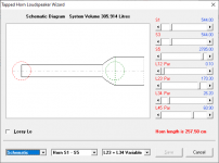
With the boxplan, I couldn't get close enough to the original simulation. So i modeled the original ROAR15 in Fusion360. My goal was to compare volumes between the 18mm vs. and a 15mm version with the original dimensions.
The Sketch in F360 included all the length-specifications and dependencies derived from the original 18mm-sketch. I then used it to calculate the inner volume (to keep it simple, I excluded the bracing, shouldn't make much difference at all) and compare it to a version, where i kept the original enclosure size and just changed the wood to 15mm. Following Circlomanens advice, I kept 18mm for the baffle and thus didn't include the baffle cutout in the volume calculation.
Results were somewhere additional ~10liters, if I were to just swap to 15mm without adapting the overall dimensions. I wouldn't have thought it was such a difference!
The original 18mm-version:

I then tweaked the 15mm version, to match its inner volume to the 18mm as much as possible. I came up with something as close as can get - ignoring the bracing and baffle cutout. The inner volume of the adapted version is 308,2l compared to original 308,3l.

Regarding the dependencies, through changing to 15mm, theres two competing distances: 1) 648mm measuring from port to port (the piece between outer and inner braces)
2) 512mm reso to reso (the most inside pieces, forming the walls of the resonator. I had to make a compromise there and decided to change them to 646mm and 516mm, because that gave the closes approximation to the original volume.
You find a cutting list and cutting sheet for the 15mm version with 18mm baffle attached.
Once I get to buy new wood, i will build one - the tablesaw is hungry already! 🙂
The Sketch in F360 included all the length-specifications and dependencies derived from the original 18mm-sketch. I then used it to calculate the inner volume (to keep it simple, I excluded the bracing, shouldn't make much difference at all) and compare it to a version, where i kept the original enclosure size and just changed the wood to 15mm. Following Circlomanens advice, I kept 18mm for the baffle and thus didn't include the baffle cutout in the volume calculation.
Results were somewhere additional ~10liters, if I were to just swap to 15mm without adapting the overall dimensions. I wouldn't have thought it was such a difference!
The original 18mm-version:
I then tweaked the 15mm version, to match its inner volume to the 18mm as much as possible. I came up with something as close as can get - ignoring the bracing and baffle cutout. The inner volume of the adapted version is 308,2l compared to original 308,3l.
Regarding the dependencies, through changing to 15mm, theres two competing distances: 1) 648mm measuring from port to port (the piece between outer and inner braces)
2) 512mm reso to reso (the most inside pieces, forming the walls of the resonator. I had to make a compromise there and decided to change them to 646mm and 516mm, because that gave the closes approximation to the original volume.
You find a cutting list and cutting sheet for the 15mm version with 18mm baffle attached.
Once I get to buy new wood, i will build one - the tablesaw is hungry already! 🙂
Attachments
Last edited:
Great job on the 15mm conversion, those few mm's here and there wont make any difference, I guess the depth of the front QW resonator is roughly the same as the original (L45 segment, 716mm from the driver baffle to the aperture)?
Great job on the 15mm conversion, those few mm's here and there wont make any difference, I guess the depth of the front QW resonator is roughly the same as the original (L45 segment, 716mm from the driver baffle to the aperture)?
Yes, exactly! I also wanted to provide plans, but drawing in F360 is terrible, at least for my part.
Drawings would be nice but let's see how the build works out first, many times alot of details becomes clear during a build that is not emediatly apparent on the drawingboard (or CATIA in my case), when circlomanen made the first build of a ROAR12 he changed alot of this for the better when it comes to brace positions and meetings between various panels to allow for tolerances without impacting dimensions depending on them, this was very valuable and we later implemented these findings into the CAD and drawings now published.
It would be good to benefit from the job you have done regarding the 15mm conversions, what pieces where altered and how much etc. and I you feel that the build meets your expectations then perhaps we can make some notes or a list to aid other presumptive builders keen on a 15mm version, if that is ok with you?
It would be good to benefit from the job you have done regarding the 15mm conversions, what pieces where altered and how much etc. and I you feel that the build meets your expectations then perhaps we can make some notes or a list to aid other presumptive builders keen on a 15mm version, if that is ok with you?
With the boxplan, I couldn't get close enough to the original simulation.
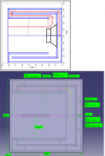
This got me curious, so I went and had a further look. It seems that the BoxPlan sheet gets it right for S1, S2, S3, L12 and L23 (accounting for the slightly different layout), S4 and S5, but the deviation occurs at L34 and L45, and it's due to the way that the path is analyzed. BoxPlan analyzes it as a mirror-imaged path along the center, but the ROAR image from their website puts L45 and L34 at the center of the path (see attached image).
So, which approach is more correct? Hmm...
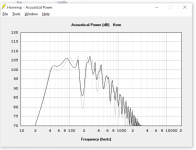
Does anyone have a measured impedance curve for the ROAR15?
Attachments
I believe (but I'm not sure) that perhaps the L45 depiction in your box plan sheet is more accurate, this since it might be so that only the fully enclosed volume is the one making up the QW resonator, and if so this is staring after the tapping (the openings into the resonator).
The question (and this was initially never fully resolved) is how the L34 transition should be set up, granted the L34 transition in the cad image might be slightly to long since the coupling (or summation) may not occur at the center of the driver, even though this is how you traditionally set it up.
I also see you adopt the advanced centreline method which has proven to be very accurate, in our case we let CATIA set up a natural flow line with neutral tension to describe the corner so we might loose some length there, I'm not sure which is best.
Last edited:
Another way to determine which approach is more correct is to look at what the Hornresp sim says about the net volume of the horn. And usually it's best that, if there's a difference, that the sim show a volume that's slightly smaller, rather than larger, than the actual net volume of the built horn.
This means that either (1) the sim on Martinsson's site is off a bit, or (2)both the Boxplan sim and the Boxplan estimate of net box size is off. I think the former might be more likely, as it's fairly easy to calculate net box size, so unless I made a REALLY big mistake in the Boxplan workbook... 🙂
- The calculated box volumes in Boxplan work out to be 390 liters gross (using the external dimensions) and 308 liters net volume (external volume minus the volume of the panels that make up the box).
- The corresponding Hornresp sim generated by Boxplan, with cone compensation turned off, puts the net volume at about 305 liters, a -1% error).
- The ROAR15 sim off of Martinsson's site puts the net volume at 347 liters, a +12.7% error (and the layout of the horn in the built ROAR15 doesn't occupy the entire box, so the real error is slightly higher).
This means that either (1) the sim on Martinsson's site is off a bit, or (2)both the Boxplan sim and the Boxplan estimate of net box size is off. I think the former might be more likely, as it's fairly easy to calculate net box size, so unless I made a REALLY big mistake in the Boxplan workbook... 🙂
Attachments


I believe (but I'm not sure) that perhaps the L45 depiction in your box plan sheet is more accurate, this since it might be so that only the fully enclosed volume is the one making up the QW resonator, and if so this is staring after the tapping (the openings into the resonator).
The question (and this was initially never fully resolved) is how the L34 transition should be set up, granted the L34 transition in the cad image might be slightly to long since the coupling (or summation) may not occur at the center of the driver, even though this is how you traditionally set it up.
I think the method used in your sim puts S4 closer to the right location, but results in a sim volume that's higher than net box volume, which means that the horn's lowest resonance frequency will be a bit higher than the sim suggests.
OTOH, the method used in my sim seems to get the net box volume correct, but puts the mouth tap (S4) off a bit from where it actually is, which means that while it should give a better estimate for the horn's lowest resonance frequency, the sim might be off a bit at the upper end of the passband.
I suspect that using Hornresp's "stepped horn" feature and moving the tap to S3 (by setting the sim type to "TH1") and using S2-S3 to represent the section by the driver might produce a sim that's closer to the build. The mouth "tap" will still be off a bit, but the error will be a lot smaller.
So finally I got the 15mm version built. The conversion happened to work out just fine. Still, it is a heavy enclosure! I definetely prefer it this way over a even heavier 18mm build. I will post pictures for size to size comparison with a THAM15, once I get to set them up and do measurements, which I will provide here.
After sanding and edge routing the thing today, I fired it up for a quick test. Boy, it does have punch! I liked the overall first impression. After a bit of fiddeling it integrated nicely with my tops and sounded nice. Some EQ on the 90h peak helped it roar less, because on some music, the bass notes sounded kind of honky. The quick guess EQ helped on that.
I couldn't feed it full 1200Watts yet (15TBX100 8Ohm mounted), since I did not want to upset my neighbours. Going half way, it already had a lot of smack and chest punch, and noticeably louder than a THAM15.
Funk music played very musical on it. But best use I guess is for some serious techno, aka YouTube.
Nice to hear back from you xrtze, and to hear that your 15mm build went well.
Thanks for posting your impressions but I'm a bit concered about you having to apply eq in the 90Hz region and that you describe the sound as honky, perhaps I can help out in finding out why this is the case.
Are they brand new?
The reason for asking is that some of the T/S params. may not have settled on published specs yet, a brand new driver might overpronounce the upper part of it's working range until the suspensions soften up, this is normally not a major contributor though.
What processing is applied?
In combination with with above a to high crossover point and/or to shallow filter slope may lead to yet even more of the upper working range being heared.
I expirience a difference in tonal characther if crossed over at 160hz or 120hz with the same slope and filter type (48dB/Oct LR) where the higher cross over point adds some of the properties you describe but at the same time it adds even more punch, with some care and attention to the integration I actually prefer this, but it may also be inflenced by a favourable acoustic environment in my case.
Please let us know more about how you expirience them, take care and stay healthy, br / Anders
Hey Anders,
no, these are not brand new, they did their duty on the THAMS already with 1000W over a few hours. Regarding the honk, nothing to be concerned about to much I guess. I also changed the crossover at the same time applying EQ, because there was quite some overlap, so I guess phase Issues as well. Crossed over relatively low at 110hz with 24LR. All without measurements and just a quick guess, so lets wait for the measurements 🙂
Btw, for measuring impedance, what is the procedure?
- Home
- Loudspeakers
- Subwoofers
- ROAR15