Roender, The original schematic at the beginning of the post only shows 5 of the thermal trac diodes connected in the diode string. Where is the sixth thermal trac diode connected? Tad
Roender, what's the spec for D7 and D8 in your front end power supply?
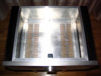
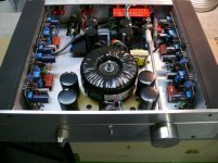
What is the dimension of the heat sink? do you think it is the right size? or you would go bigger/smaller?
What is the dimension of the heat sink? do you think it is the right size? or you would go bigger/smaller?
Hi,
only just found and couldn't stop reading this thread.
Roender,
Superb.
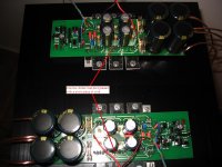
Could the quality of sound be, in part, due to the very few capacitors in this design, nine in all? There are twice as many transistors (18) excluding the 6output devices and almost all of these are high fT and high hFE.
only just found and couldn't stop reading this thread.
Roender,
Superb.
Could the quality of sound be, in part, due to the very few capacitors in this design, nine in all? There are twice as many transistors (18) excluding the 6output devices and almost all of these are high fT and high hFE.
niner said:Roender, what's the spec for D7 and D8 in your front end power supply?
What is the dimension of the heat sink? do you think it is the right size? or you would go bigger/smaller?
http://www.diyaudio.com/forums/showthread.php?postid=1354022#post1354022
The heatsink has 0.37C/W (300x150x25mm).
AndrewT said:
Could the quality of sound be, in part, due to the very few capacitors in this design, nine in all? .
😉
Thank you Andrew.
Hi niner,
I make a little mistake in the frontend PSU BOM, it is a 36V zener diode, not 39V.
Thanks,
Mihai
I make a little mistake in the frontend PSU BOM, it is a 36V zener diode, not 39V.
Thanks,
Mihai
Thanks Mihai.
I have most of parts in my procession. Only things I need is PCBs and transformers. Hopefully I can start the build in a week.
I have most of parts in my procession. Only things I need is PCBs and transformers. Hopefully I can start the build in a week.
DRZ1 said:Roender , very good job.
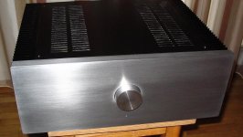
why not mounting the pot at the back and use a extention rod ? I do it like that with my Symasym.
Personaly i prefer black.
Thank you Denis
Your case is very nice too.
I will put a DAC inside, monted in front of the case and very close to the volume pot.
This amplifier will have digital inputs only.
Mihai
Hello everybody, my first post on this forum!
@roender I'm mesmerised ! Congratulations for an excellent amp, I'm really impressed by your skill and knowledge!
I have a few questions about your design. I hope they don't sound stupid, but i am a newbie in electronics and I have quite a hard time trying to understand how amplifier work. So why have you chosen higher supply voltages for the input stage than for output stage? Why is the current source Q17,D8 and R20 connected to the anode of D17(and not the positive supply rail)? What is the purpose of C7?
Thanks in advance for the answers. Maybe you could point to me some good sources of information about amplifiers and electronics.
Once again I congratulate you, and I wish you good luck on your projects!
Hi Emanuel,
The only stupid question is the one you don't ask.
Are you doing EE at Politehnica Bucuresti?
Way bigger rail voltage in front than in output stage? It's a folded cascode design, with limited voltage swing in "VAS" at cascode base reference voltage.
"Why is the current source Q17,D8 and R20 connected to the anode of D17 ?
That's a very good question! You are the only one who see that and ask about reasons.
The firs stage is a class A stage and I like to have symmetrically currents in every class A stage I design, with as little as possible return currents to ground, to keep the zero reference clean.
The role of C7 is to slow down voltage response in output stage bias circuit.
Mihai
You amplifier sounds so good that i would be happy with them even inside those
Card boxes used for shoes.
Carlos
Card boxes used for shoes.
Carlos
Thanks for the answer! I see that your design is more clever than i thought! I really like your way of implementing current sources. Fancy that!😉 . Now i see that a good amplifier has a lot of "secrets" and much thinking and work behind. Keep up the good work!
About Politehnica Bucuresti, you came close. I'm doing Automatics.
About Politehnica Bucuresti, you came close. I'm doing Automatics.
- Home
- Amplifiers
- Solid State
- RMI-FC100, a single stage audio power amplifier