Looking at the Sapphire PCB, less than 20% of the area is taken up by the resistor outlines. Moving to 1/8W resistors would reduce that area by less than half, so you'd save perhaps 10% on board area. Probably not worth the effort.
A full SMT version of the Sapphire, on the other hand, would be interesting. Even then though there are fairly robust limits to how small you can make it since the electrolytic capacitor size can't be reduced significantly.
A full SMT version of the Sapphire, on the other hand, would be interesting. Even then though there are fairly robust limits to how small you can make it since the electrolytic capacitor size can't be reduced significantly.
Hi guys, I have a question.
If I choose a lower gain, will voltage needed decrease too? I want to run it on +/- 12V or +/- 9V, for a more portable design. I'm noob at power stage so please don't be too harsh on me.
Cheers!
If I choose a lower gain, will voltage needed decrease too? I want to run it on +/- 12V or +/- 9V, for a more portable design. I'm noob at power stage so please don't be too harsh on me.
Cheers!
The gain has nothing to so with the power supply voltage.
The higher the headphone impedance, the more voltage gain you need.
The power supply voltage sets how much power you can deliver into a given load.
The Sapphire circuit is configured to work with 12 VAC secondaries, delivering about 17 V DC to the board (V++) which is regulated internally to about 11.4 V (V-).
If you were making a portable version with batteries, you'd bypass the regulator and feed 9 V directly to V+. The amp part of the circuit would work fine, but the current drain would still be 70-80 mA for the stereo circuit, whether or not you were playing music. That's because of the class A output stage. Battery life will be very short.
I'm just getting the parts together for this build. I think I've got everything but could anyone point me to a part number for the black terminal blocks please? I can only seem to find the ubiquitous green ones and I've ordered black PCBs.
I'm just getting the parts together for this build. I think I've got everything but could anyone point me to a part number for the black terminal blocks please? I can only seem to find the ubiquitous green ones and I've ordered black PCBs.
I think these should be right.
For 3 positions you can use this one, while for 4 positions you can join the ones with 2 positions.

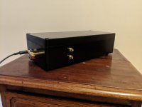
Nice finish on the case, btw. Very monolith.
Thanks Richard.
A can of black gloss is all it is. It's very moody looking though in the flesh 😀
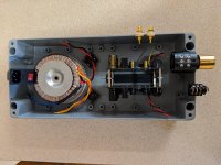
I know I'm not the best example of your advice to use a larger enclosure than you think you'ill need but I couldn't resist this box. It will be a tight fit, adjustments will need to be done prior to fitting the boards and then there's the divider/shielding between power and audio sections to devise. I'm hoping the strays from using a larger transformer doesn't complicate matters any. Anyway we'll see... It all comes down to how accurately I've measured... but I have no doubt I will have a few moments for sure.
Q.
I have fitted a pot I had on hand, EIZZ 100k. Will this at least get me up and running? It will eventually be replaced...
Thank you and cheers,
Dennis
It looks fairly spacious, especially since you can stand the boards vertically.
That pot will work fine. Why not?
That pot will work fine. Why not?
It looks fairly spacious, especially since you can stand the boards vertically.
That pot will work fine. Why not?
Good news about the pot. Thanks Richard.
The internal height of the enclosure is 83mm but I'm more concerned about the length. At 353mm (internal length), each of the components are still spaced close. For example I lose 9mm from that length for a separator panel (steel) but I actually lose closer to 22mm allowing for clearance either side of the divider. And so it goes.
In the end I'll just have to make it fit.
Dennis
Ok so a quick wire up and there's a problem. I suspect the pot so I'll switch it out for another before I do anything else.
I found an interesting design on Taobao. Diamond buffer with A970/C2240 on input stage and A1360/C4323 on the output stage.
An externally hosted image should be here but it was not working when we last tested it.
An externally hosted image should be here but it was not working when we last tested it.
You can find similar stuff on eBay. Note it's just a diamond buffer, 4 transistors per channel, no current sources, no nuffink.
Hello everyone.
Thank you Richard for a great project. My version is 41m. Amp works without C1 and without volume control, 40 mA bias current, closed loop buffer configuration.
I would like to ask if adjustable gain can be realized with only R2, or if you can also change R3X ? What consequences does changing the R3X have for the stability amp? I noticed that the change of R2, apart from gain, also slightly changes the tonal balance.
What is the typical level of output impedance Sapphire4 ?
Thanks.
I would like to ask if adjustable gain can be realized with only R2, or if you can also change R3X ? What consequences does changing the R3X have for the stability amp? I noticed that the change of R2, apart from gain, also slightly changes the tonal balance.
Please refer to the BOM, specifically the gain calculator worksheet for R3X. YOu can see from the table that the gain can be adjusted from 6 to 27 dB just by changing R2. The stability margin decreases as the gain is reduced, but these condifurations are all theoretically stable and have been practically verified to be so. Since distortion is reduced at low gain due to the greater feedback, its natural for the tone to change slightly, and there are other factor too which could mean the sound changes a little.
What is the typical level of output impedance Sapphire4 ?
Open loop (R3) it's about 2-3 ohms, iirc, defined by the emitter resistors R17-18. Closed loop (R3X) it's less, how much less depends on the gain setting.
For my next build I was thinking of going with the stacked board approach as well and use a slim case.
The issue here is that the inputs from the rear pass right by the toroidal transformer....
How about housing the transformer alone in a separate small box and transferring AC via umbilical cord to the main chassis? The main chassis will house the rectifiers.
The issue here is that the inputs from the rear pass right by the toroidal transformer....
How about housing the transformer alone in a separate small box and transferring AC via umbilical cord to the main chassis? The main chassis will house the rectifiers.
I'd put the rectifiers as the box with the transformer. Route V++, V--, and COM through the umbilical as per the standard Phonoclone/Emerald builds.
One idea I have been toying with on paper recently is to build the Sapphire in a 150 mm dia. pipe, about 300mm long. boards are back-to-back, the transformer is attached to the back cap of the pipe, the controls on the front cap.
One idea I have been toying with on paper recently is to build the Sapphire in a 150 mm dia. pipe, about 300mm long. boards are back-to-back, the transformer is attached to the back cap of the pipe, the controls on the front cap.
- Home
- Amplifiers
- Headphone Systems
- RJM Audio Sapphire Desktop Headphone Amplifier