Ecce musica.
My Emerald is working now in MM configuration and liking what I hear.
So far it looks more transparent and linear than my dual diy ECC83 phono stage.
There's a bit of noise cranking up the volume with an MM cart on (I did not try it with shorted inputs yet) but it is promising.
With boards from MRA with smd components, hotrodded voltages to the opamps are set to 14,8VDC/15,2VDC from a 23VDC CRC power supply (trafo is dual 15V and R20,R21 increased from 10k to 12k). It looks the temps are still cool and safe.
Thanks a lot @rjm Richard for this great project!
Hopefully I am able to post some pics, ps I have no pic with finished internal wiring though.
Attachments
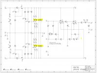
Hi Richard, Need your advice. What resistor value for R3 & R4 to achieve gain 47db(MM) / 57db(MC). Thanks Lone.
Richard, Are the R3 to adjust the gain for MC & R4 for MM?That would be R3=110 ohm and R4=274 ohm.
So, It means value of R3 & R4 is the gain of MC? How about the MM gain? I can see the open of JP1_2 are only connected the R4 to the ground. Are the R4 value reflects the MM gain?Not quite. The resistance for MC is R3||R4 so 78 ohms effective.
I will be using an external PSU that provides ultra low noise +/- 12V.
I will be wiring them to the V+, V- and REF pads, or to the relevant pad in Q5 and Q7.
I will be omitting the marked section in the PCB, but my question is whether I should also omit C6-C13 or are they required for local bypass?
I will be wiring them to the V+, V- and REF pads, or to the relevant pad in Q5 and Q7.
I will be omitting the marked section in the PCB, but my question is whether I should also omit C6-C13 or are they required for local bypass?
Attachments
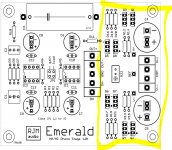
"Required" is strict wording, but yes, these bypass caps are recommended to include to maintain op amp stability.
Hello everyone
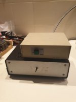
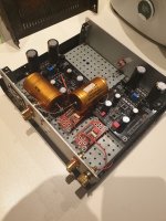
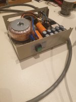
I'm finally working on my Emerald, having finished the power supply, I haven't finished the Emerald chassis yet.
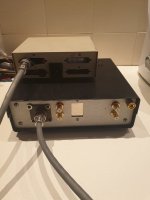
The power supply follows the dual mono philosophy and is connected to the Emerald chassis by cable.
And here is the time when I wanted to ask a question to Richard, the multiconductor cable I am using has a shield, should I connect the shield to the GND of the boards (it is not connected to the power supply) or is it unconnected?
Or is it about experimenting and testing?
Here are some images of the power supply and one of what would be my intention for the rear of the Emerald chassis, but I have already simplified this intention in the meantime.
The switches on the pcb-switch board that would be accessible through two "windows" will only be accessible from the inside, as the pcb switch will face inwards.
Later I will post developments on the completion of the Emerald chassis.
My thanks to everyone, especially Richard and a happy new year to everyone.
Best regards
Carlos
I'm finally working on my Emerald, having finished the power supply, I haven't finished the Emerald chassis yet.
The power supply follows the dual mono philosophy and is connected to the Emerald chassis by cable.
And here is the time when I wanted to ask a question to Richard, the multiconductor cable I am using has a shield, should I connect the shield to the GND of the boards (it is not connected to the power supply) or is it unconnected?
Or is it about experimenting and testing?
Here are some images of the power supply and one of what would be my intention for the rear of the Emerald chassis, but I have already simplified this intention in the meantime.
The switches on the pcb-switch board that would be accessible through two "windows" will only be accessible from the inside, as the pcb switch will face inwards.
Later I will post developments on the completion of the Emerald chassis.
My thanks to everyone, especially Richard and a happy new year to everyone.
Best regards
Carlos
Attachments
-
![P_20211115_210853[2].jpg](/community/data/attachments/919/919748-37a3d1bcd00e1a597d1806c3318294ca.jpg?hash=N6PRvNAOGl) P_20211115_210853[2].jpg86.3 KB · Views: 359
P_20211115_210853[2].jpg86.3 KB · Views: 359 -
![P_20211202_212519[1].jpg](/community/data/attachments/919/919749-572a7352736e4b3476acbf01e9b53653.jpg?hash=VypzUnNuSz) P_20211202_212519[1].jpg164.8 KB · Views: 324
P_20211202_212519[1].jpg164.8 KB · Views: 324 -
![P_20211202_212614[1].jpg](/community/data/attachments/919/919750-3cf3be723efb8b7c8faca19bdbaf0636.jpg?hash=PPO-cj77i3) P_20211202_212614[1].jpg147.7 KB · Views: 266
P_20211202_212614[1].jpg147.7 KB · Views: 266 -
![P_20211202_212756[1].jpg](/community/data/attachments/919/919751-63d81fc4f8182eef07e21766d2086a39.jpg?hash=Y9gfxPgYLu) P_20211202_212756[1].jpg121.3 KB · Views: 263
P_20211202_212756[1].jpg121.3 KB · Views: 263 -
![P_20211202_212822[1].jpg](/community/data/attachments/919/919752-418bbe0239ae737d83a79bfdb79fc830.jpg?hash=QYu-Ajmuc3) P_20211202_212822[1].jpg98.3 KB · Views: 253
P_20211202_212822[1].jpg98.3 KB · Views: 253 -
![P_20211202_212839[1].jpg](/community/data/attachments/919/919753-9c2f50af0505f0b14ad9c6b8cf36770e.jpg?hash=nC9QrwUF8L) P_20211202_212839[1].jpg66.7 KB · Views: 240
P_20211202_212839[1].jpg66.7 KB · Views: 240 -
![P_20211202_212919[1].jpg](/community/data/attachments/919/919754-d4a5d3953988859fdf4918131969e767.jpg?hash=1KXTlTmIhZ) P_20211202_212919[1].jpg52.7 KB · Views: 306
P_20211202_212919[1].jpg52.7 KB · Views: 306 -
![P_20211202_213554[1].jpg](/community/data/attachments/919/919755-847fb2dff173abeaa8fe91bf206688e0.jpg?hash=hH-y3_Fzq-) P_20211202_213554[1].jpg154.2 KB · Views: 420
P_20211202_213554[1].jpg154.2 KB · Views: 420
Hi Carlos,
You have a two different options with the shield connection.
1. Connect it to the chassis at both the power supply and phono stage sides. This arrangement gives the same electrical connection as the one-chassis builds. The phono stage chassis is now connected to earth because the power supply is now connected to earth. The potential issue here is the system may also be connected to earth via. the amplifier, which can lead to ground loops.
2. Connect it to the power supply side only. This arrangement retains the electrical connection of the two-chassis build, which leaves the phono stage chassis un-earthed (but connected to circuit ground, which is normally earthed at the amplifier). It is what I consider the safer option from the point of view of avoiding potential grounding issues.
My advice would be to wire it as (1) first, and try disconnecting it at the phono stage if you have any hum problems.
Richard
Just finished another Emerald build, full dual mono psu, one box build. She's sounding very good. There's a little bit of roar audible with the needle up at my usual playback volume on my pre, but only audible 12 inches away from my speakers.
I reckon that's about -70db, which is very decent for a one box build, no hum at all.
I reckon that's about -70db, which is very decent for a one box build, no hum at all.
I've been playing around with opamps. Ended up with the obsolete maxim 427, 0p27 variant, in the mm end and an opa 1611 in the front. Feels maybe a touch more dynamic and with less glare at the top than using op27 is both slots.
Hi all, back again as I decided to try the 10ohm resistor ground lift trick mentioned by Nikos (post 606) and suggested by Richard. Since I last posted, I've rejigged the layout of the rectifiers (which helped the hum a lot), and fitted the chunky Jantzen's, which was like going from 720p to 1080p 🙂 The hum is only really audible when I get up close to the speakers and have the output at about just over my normal listening level or above. Anyway, thought it was worth a shot.
So I quickly tried soldering a single 10ohm (5W) resistor to the GND wires which are already twisted and soldered together. It doesn't seem to make a noticeable difference. Do I need to spit the individual GND wires and solder a 10ohm resistor to each, then clamp to the Earth screw?


So I quickly tried soldering a single 10ohm (5W) resistor to the GND wires which are already twisted and soldered together. It doesn't seem to make a noticeable difference. Do I need to spit the individual GND wires and solder a 10ohm resistor to each, then clamp to the Earth screw?

Hi Jag, Here are some solutions that you can try to eliminate the hum issue.Hi all, back again as I decided to try the 10ohm resistor ground lift trick mentioned by Nikos (post 606) and suggested by Richard. Since I last posted, I've rejigged the layout of the rectifiers (which helped the hum a lot), and fitted the chunky Jantzen's, which was like going from 720p to 1080p 🙂 The hum is only really audible when I get up close to the speakers and have the output at about just over my normal listening level or above. Anyway, thought it was worth a shot.
So I quickly tried soldering a single 10ohm (5W) resistor to the GND wires which are already twisted and soldered together. It doesn't seem to make a noticeable difference. Do I need to spit the individual GND wires and solder a 10ohm resistor to each, then clamp to the Earth screw?
View attachment 1031529
View attachment 1031530
Can you lift the switch board off the floor at all, to put more distance between the wires from the diodes.
Gave it a go with some bigger stand-offs, so there's now about 30mm between them. Doesn't seem to make a difference, but at least access to the Switchboard is improved 🙂Can you lift the switch board off the floor at all, to put more distance between the wires from the diodes.
What sort of diodes and capacitor would be required for the DDRC you mentioned previously @sq225917 ? And where exactly should I be sticking it? Given the 10ohm resistor above didn't seem to make a difference on its own, would that suggest the DDRC would be ineffective or are the diodes the critical missing piece(s)?
I'm leaning towards coupling being the source of the hum rather than a ground loop. Ground loops are easily checked - just temporarily disconnect the AC ground from the chassis. If that solves the hum, then you need to think about things like the 10 ohm resistor or other ground lift tricks. .. if there's no change then the problem is most likely the close proximity of the diodes, transformer, and AC wires to the phono amplifier circuits and, in particular, the coupling caps which make great antennas for picking up that kind of interference. Remember to evaluate hum with a dummy cartridge load on the input to rule out upstream problems.
I just swapped back in my Emerald Phono-Stage back in to my newly built system with less overall gain structure. I'm finding that my volume setting has to be increased substantially to enable my 0.3mV cart to reach appropriate volume.
In reviewing the worksheet it looks like I should change
R1 to 1000Ω
R2 to 110Ω
R3 to 22.1Ω
R4 to 47.5Ω
R5 to 1.5KΩ
Is this correct? And will it make substantial difference if I use 100Ω for R2 and 47Ω for R4?
TIA
Dave
In reviewing the worksheet it looks like I should change
R1 to 1000Ω
R2 to 110Ω
R3 to 22.1Ω
R4 to 47.5Ω
R5 to 1.5KΩ
Is this correct? And will it make substantial difference if I use 100Ω for R2 and 47Ω for R4?
TIA
Dave
Hi Dave,
First, recognize that the problem is that your new preamp/amp doesn't have enough gain. The solution is to use a preamp/amp with more gain.
Cranking the gain on the Emerald compensates for the problem, it doesnt solve it. (because it only addresses that one source component - switch another phono stage, you are back to square one)
A 0.3 mV cart should be compatible with a standard MC phono stage, which have voltage gains 35-40 dB typical. I dont recommend making the gain much higher than that - it reduces the clipping headroom. If you insist, however, you can adjust by changing the resistor R3. No other resistors need to change. Reducing R3 by half increases the gain by 6dB. I would not go past 45 dB though. Instead, I would look at using a different line stage.
Gain is necessary. Removing gain from the amp/preamp and kicking it back to the phono stage might simplify your downstream circuits, but the cost is returned with interest if you try to add it to the front end.
- Home
- Source & Line
- Analogue Source
- RJM Audio Emerald Phono Stage Help Desk