A quick word on caps. The Bennic caps are just acceptable, and I strongly recommend upgrading to something better. That said, a lot of expensive caps are aimed at tube amps and have very high voltage ratings, like your 800V Jantzen. That's not a problem exactly, but it does mean the cap is larger and more expensive than it needs to be.
If you can, try to find something that is of high quality but still comes in convenient 200 V voltage models.
At first I was thinking a set of Mundorf M-Cap Supreme, but they are all around 1000vdc. Then I found the Fostex CS at 240vdc which is recommended but it’s about €65 a piece.
Do you have any other recommendations?
Up and running!
I'm very happy with it. Even with a brand new cartridge and new caps in the preamp it sounds better than playing Tidal through my USB DAC.
I'm sure that over the next week or so it will start to bloom, as we used to say.
System:
Tubelab SSE w/EL34's
20yr-old Music Hall MMF-5 - the original belt is still good.
AT-VM95SH - I'll buy an ML stylus, too, and compare.
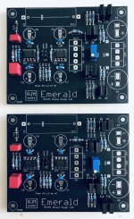
RJM Emerald
Buschhorn MK II horns's w/Fostex 4" FE108EZ's
It's a very "basic" setup with only a single volume control, the way I like it.
Thanks Richard for offering your kits and providing great support!
I'm very happy with it. Even with a brand new cartridge and new caps in the preamp it sounds better than playing Tidal through my USB DAC.
I'm sure that over the next week or so it will start to bloom, as we used to say.
System:
Tubelab SSE w/EL34's
20yr-old Music Hall MMF-5 - the original belt is still good.
AT-VM95SH - I'll buy an ML stylus, too, and compare.
RJM Emerald
Buschhorn MK II horns's w/Fostex 4" FE108EZ's
It's a very "basic" setup with only a single volume control, the way I like it.
Thanks Richard for offering your kits and providing great support!
Attachments

I forgot to add that this setup is dead quiet. I'm not hearing any hum or noise at all. I have the preamp sitting behind my turntable, up against the wall, and the power supply chassis is a couple of feet away, sitting on top of the right speaker cabinet. Maybe not the best configuration, but, as I said the system is silent even with the amp volume turned up. I'm really impressed with the Emerald.
Glad to see you got it up and running, and thanks for the report & photo.
Nice tube amp by the way. I like the blue endbells.
/R
re. caps.
€65 is a bit rich for me. I generally prefer Multicap (PPMFX) for the Emerald, but Mundorfs (Supreme) are good, as well as the Audyn KP Sn.
Nice tube amp by the way. I like the blue endbells.
/R
re. caps.
€65 is a bit rich for me. I generally prefer Multicap (PPMFX) for the Emerald, but Mundorfs (Supreme) are good, as well as the Audyn KP Sn.
hello everyone! I have received everything, and since it's my first PSU build, I would really like to double check everything with you guys. It will look like a beginner question, yet I am a bit afraid of working with main power so, I need your help 🙂
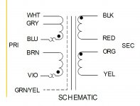
transformer is setup to 240V. So, input should be white and violet that I wire to the toggle switch.
Then I have a wire that goes from the other pole of the switch to the L of the IEC.
blue brown from the transformer (Jumper? what do they mean?) goes to Neutral of the IEC.
ground from the IEC is tied to chassis and with ground from transformer.
from V++ I have a wire to resistor then led+
from com+ I have a wire to led-
XLR wiring is wrong, I will correct it: V++ should got to 2, V-- to 3 and COM to 1
Is this correct?
Attachments

My Emerald project is coming along slow and steady. Waiting for the next order from Mouser, a couple of Nichicons items on backorder 'til September 🙂
I soldered the opamps directly to the board since I happened to order something totally else than the dip8. Will this matter when I do any testing further on?
What kind of wires do you prefer to use for the internal connections?
I soldered the opamps directly to the board since I happened to order something totally else than the dip8. Will this matter when I do any testing further on?
What kind of wires do you prefer to use for the internal connections?
Attachments
...blue brown from the transformer (Jumper? what do they mean?) goes to Neutral of the IEC...
Is this correct?
Hi ldarieut. No.
Connect White to L and Violet to N (or, the other way around).
Twist and solder the Blue and Brown wires together and insulate well with heat-shrink tubing. Neither of these two wires connects to anything except each other.
I did not connect my Green/Yellow shield wire to ground. I just insulated the end and tucked it away. But, it's probably a good idea to do so.
I hope this helps.
@KeLLoGsX
The global shortages are starting to bite, I'm noticing all kinds of things are out of stock recently which are normally always available. With the Nichicons see the BOM for alternates, and of course any electrolytic (preferably audio use) can be used as long as they have the right lead spacing.
Soldering the opamps directly to the boards means you can't easily try different ones, of course, but as long as they are working there is no real need to use sockets.
People always ask what they should use for the internal wiring. As far as I am concerned it doesn't matter. Use whatever is convenient. I like 28 ga. solid core copper twisted pairs, from LAN cable.
@ldarieut
Please be very careful with the transformer connections. This is not "try and see", as you are playing with dangerous high voltages.
The 240 V connection is "Input to White and Violet, jumper Blue & Brown". So AC live goes to violet, AC neutral goes to white, and the blue and brown wires join together but don't connect to anything else. Your switch will insert into the live, so the tranformer violet goes to the switch, and the other side of the switch connects back to the IEC and fuse.
Attachments
Last edited:
Although, you have to cut a larger hole in your chassis, I recommend using these all-in-one receptacles with power switch and fuse holder: https://www.mouser.com/ProductDetai...ZRnZqo5Zedg==&countrycode=US¤cycode=USD
There are only three solder connections: Line, Neutral and Earth Ground. The drawback is that your power switch can't be on the front of the chassis. But, that's never mattered to me. 🙂
There are only three solder connections: Line, Neutral and Earth Ground. The drawback is that your power switch can't be on the front of the chassis. But, that's never mattered to me. 🙂
Attachments
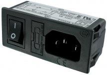
Although, you have to cut a larger hole in your chassis, I recommend using these all-in-one receptacles with power switch and fuse holder: https://www.mouser.com/ProductDetai...ZRnZqo5Zedg==&countrycode=US¤cycode=USD
There are only three solder connections: Line, Neutral and Earth Ground. The drawback is that your power switch can't be on the front of the chassis. But, that's never mattered to me. 🙂
Yes, I agree - using a similar one from Schurter.. However it's not internally wired like the one you link, and it was more expensive

Thank you for all your answers and advices!
I have a "all in one" iec socket, but I would like to be able to power it from the front.
I am quite proficient with microcontrollers and code.
Yet, it is the first time I dabble in 240v power, I have alway managed to stay below 24v in all my diy projects, hence I am maybe over-carfeful!
I have a "all in one" iec socket, but I would like to be able to power it from the front.
I am quite proficient with microcontrollers and code.
Yet, it is the first time I dabble in 240v power, I have alway managed to stay below 24v in all my diy projects, hence I am maybe over-carfeful!
dc reading out of the DBRB v++/COM is +10V V--/COM is -10V
is this correct? I thought it would be +/-12v ?
is this correct? I thought it would be +/-12v ?
nevermind, it was the quality of my spades 😡 .dc reading out of the DBRB v++/COM is +10V V--/COM is -10V
is this correct? I thought it would be +/-12v ?
I have 11.8 -11.8
The expected values are +- 18V. You won't measure that until the emerald is connected however. Without the filter caps connected you'll see about 10V. Don't worry about this.
Thank you.😱The expected values are +- 18V. You won't measure that until the emerald is connected however. Without the filter caps connected you'll see about 10V. Don't worry about this.
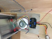
Almost there. I will wait for someone else to be in the room before I plug it 😉
What should I do with the spare grey wire ? Put some heat shrink on it and tuck it away?
What should I do with the spare grey wire ? Put some heat shrink on it and tuck it away?
Attachments
Last edited:
Yes.
Also, it looks like the blue and brown wires are connected together but left exposed. That's extremely dangerous. There should be no exposed metal anywhere on the primary side.
Also, it looks like the blue and brown wires are connected together but left exposed. That's extremely dangerous. There should be no exposed metal anywhere on the primary side.
Thank you. Yes, that's correct, I have not put a heatshrink on it yet but I intend to before I power on.Yes.
Also, it looks like the blue and brown wires are connected together but left exposed. That's extremely dangerous. There should be no exposed metal anywhere on the primary side.
This doesn’t look good at all.
I have plugged the emerald and I get v+ ref at 8,75 and v- ref at -8,76 after adjusting the resistor.
V++ com entering emerald is 15v and v— com is -15v.
Opamps are plugged.
In- in+ is 0, out+ out- is 0.
Tomorrow, I will remove the added led and the toggle switch from the psu to check if these are not causing trouble…
Last edited:
- Home
- Source & Line
- Analogue Source
- RJM Audio Emerald Phono Stage Help Desk