Hi brinker, I was just looking at your photo in post #377. They do "just" fit:
RJM Audio Emerald Phono Stage Help Desk - Page 38 - diyAudio
I know very little about the various brands of audio caps, except that some cost more than my entire project did. I spent the last year building vacuum tube guitar amps where it's the speakers, and to some extent the tubes, that have the biggest effect on tone.
Thanks Richard, I actually considered these smaller 100V caps:
Jantzen Alumen, Z-Cap 2.20µF 100VDC
But, they are over 2 1/2 times as expensive at $50 each. I can always upgrade caps down the road.
I'm shopping for a new cartridge, and I'd rather put more money into that at this point. I can either buy a new stylus for my Goldring 1042 at $300, or go in a completely different direction like the MC Denon 301 MKII at around $400. Then there's the Hana EL at $475. You see my point, cartridges are marketed to keep getting you to spend an extra $100 more... 🙂
Hello Richard. I'm in the process of ordering all of the parts for another Emerald build and have a quick question. I can't seem to find C6-C9 UKZ caps in stock anywhere (where shipping isn't rediculous). Would the bi-polarized UES work OK in this situation?
Thanks
Thanks
No, dont use bipolars. Use any regular polarized electrolytic cap of the same voltage and capacitance. From nichikon, there's the KW FW and FG series.
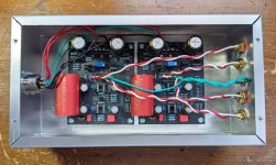
The caps arrived today, so I wired up the preamp boards. Unfortunately, I don't have time to power it up and take measurements now. It will have to wait until tomorrow. I assume it's a good idea to use my dim-bulb tester for the first power up, yes? And, of course, I still need to install the op amps and the jumpers.
Attachments
Last edited:
I think a simple smoke test is ok. With the op amps off connect the power supply then plug in the power supply. If nothing goes "bang" then you move in with the voltmeter to check that pin 4 and 7 of the op amps sockets is at the right voltage, trim with the trim pot, power off, add the op amps, power up again, wait 10-15 minutes, readjust the trim pot, and you should be good to go.
Thanks Richard. I'm not totally clear on how and where I'll be taking voltage measurements.
Do I measure from socket pin 4 to ground and then pin 7 to ground, or between 4 and 7? What voltage should I see?
Then, am I right that I measure between V+ and Ref and V- and Ref and use the trim pot to balance those reading?
Any other readings I should take?
Thanks in advance!
Do I measure from socket pin 4 to ground and then pin 7 to ground, or between 4 and 7? What voltage should I see?
Then, am I right that I measure between V+ and Ref and V- and Ref and use the trim pot to balance those reading?
Any other readings I should take?
Thanks in advance!
4-ground and 7-ground, adjust trim until equal absolute value
They should both be around 9-12 V when adjusted
They should both be around 9-12 V when adjusted
OK... I balanced the voltages with the trim pots and here's what I got.
Right Channel:
IC1 pin 4: 12.97VDC
IC1 pin 7: 12.99VDC
IC2 pin 4: 12.97VDC
IC2 pin 7: 12.99VDC
Left Channel:
IC1 pin 4: 11.95VDC
IC1 pin 7: 11.95VDC
IC2 pin 4: 11.95VDC
IC2 pin 7: 11.95VDC
Is the right channel a bit too high?
Right Channel:
IC1 pin 4: 12.97VDC
IC1 pin 7: 12.99VDC
IC2 pin 4: 12.97VDC
IC2 pin 7: 12.99VDC
Left Channel:
IC1 pin 4: 11.95VDC
IC1 pin 7: 11.95VDC
IC2 pin 4: 11.95VDC
IC2 pin 7: 11.95VDC
Is the right channel a bit too high?
Last edited:
I installed the op amps and let it bake for 20mins. I readjusted the trim pots and I have:
Right Channel:
V+ 12.89VDC
V- -12.89VDC
Left Channel:
V+ 11.92VDC
V- -11.92VDC
Right Channel:
V+ 12.89VDC
V- -12.89VDC
Left Channel:
V+ 11.92VDC
V- -11.92VDC
Attachments
Last edited:
Looks good! There is some variation L-R because the regulator output depends on the transistor characteristics, the Vbe to be specific, but its no big deal as you can trim the positive and negative halves to be equal on each board.
Got everything in the mail this morning, I don't really share your taste in food though 🙂
Got one faulty R3. I will check if I have a spare in my stock.
R22, screw goes to the circle?
Got one faulty R3. I will check if I have a spare in my stock.
R22, screw goes to the circle?
A faulty resistor would be a first. What value is it?
R22: yes, package details align with the printed outline on the boards
R22: yes, package details align with the printed outline on the boards
yes indeed, my multimeter went wrong. Measured it again this morning and it's fine. 😱
one board done, one to go...
one board done, one to go...
Last edited:
Is this layout advisable?
what use is the second COM slot?
(last bennic is not soldered)
Edited for correct wiring, post below.
what use is the second COM slot?
(last bennic is not soldered)
Edited for correct wiring, post below.
Last edited:
No, your in-/outputs are wrong.
In+/- from one board goes to one white RCA, and Out+/- on the same board goes to the other white RCA. Obviously the other board then utilise the red RCA pair.
It's fairly obvious on RJMs build photo RJM Audio - The Emerald Phono Stage
The 2nd COM slots, is if you don't join the COM line early from the bridge, and take them separately to each board - which I have done (currently don't have a photo of it).
Last edited:
yes, I realized that after watching the schema. I would like :
IN L/R OUT/LR
Thanks!
IN L/R OUT/LR
Thanks!
Attachments

Last edited:
ok, get it. thanks.The 2nd COM slots, is if you don't join the COM line early from the bridge, and take them separately to each board - which I have done (currently don't have a photo of it).
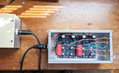
Personally I'm routing the ground post in the middle of the two RCA sets, because it looks nicer. It's unlikely to have any effect.
I'd also have the RCAs and power wiring on opposing sites.
I'd also have the RCAs and power wiring on opposing sites.
indeed, if I have the XLR on the opposite side, I will put the ground between the RCA. I'd like to keep the faceplate clean, but I understand it's less practical. Now, should I expect interferences? I have made a few amplifiers like that, and I never had any problem as long as the power cables are neatly routed along the chassis. I don't know with this preamp.Personally I'm routing the ground post in the middle of the two RCA sets, because it looks nicer. It's unlikely to have any effect.
I'd also have the RCAs and power wiring on opposing sites.
I bought a new cartridge that's supposed to arrive Saturday. After I get that installed and aligned I'll hook up the Emerald and play some records. Then I'll be able to report back on how great it sounds!
- Home
- Source & Line
- Analogue Source
- RJM Audio Emerald Phono Stage Help Desk