Removed everything and checked the output from the toroidal : both are at 12,5ac
Output after the dbrb is 14,9 and -14,9 which is what I get inside the emerald. I measured the pins of the ampop and they read +8.6 for 7 and -8.6 for 4. Same on both ampop. 🙁
Output after the dbrb is 14,9 and -14,9 which is what I get inside the emerald. I measured the pins of the ampop and they read +8.6 for 7 and -8.6 for 4. Same on both ampop. 🙁
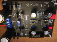
Here is the board, I hav checked the resistors and the transistors. Everything looks good to me. Sometimes I have soldered the two + pads together with the capacitors, but I don’t think it matters?
Attachments
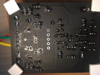
ok, I think I figured it out. I have swapped 136 and 135.
136 should go to odd, and 135 to even. Guess my brain was set on maths and not on reading the technical sheet.
Damn, that's the worst thing I wanted to desolder!!!! 😡
136 should go to odd, and 135 to even. Guess my brain was set on maths and not on reading the technical sheet.
Damn, that's the worst thing I wanted to desolder!!!! 😡
Sorry for being late to comment here. I meant to look at it this morning, but was busy with other things.
First comment is the circuit will work just fine with +\- ~9 V rails. So you may want to give it a try to see.
Second comment is
Q1,Q3,Q5,Q7 BD136 PNP
Q2,Q4,Q6,Q8 BD135 NPN
Odd part numbers are "positive" PNP BD136, even part numbers are "negative" NPN BD135. I'd be surprised that you soldered all the transistors incorrectly and the output was still more-or-less right, but I can't confirm or deny it being possible.
The output at the V+ and V- pads should be about +/-13 V. It can be reduced by changing the value of R20,21 from 10k to 6.8k or so. The output voltage will scale with the change in resistance. I say this because if your V++ V-- rails are only 15 V running at 13 V is a little tight as it doesn't leave a lot of headroom for the regulation circuit. I would recommend changing R20,21 to 7.5k or 6.8k. You can test by soldering 47k or 100k in parallel, which will temporarily lower the effective resistance by 10-20% or so.
P.s. desoldering TO-220 components is a pain. If you don't have the right tools it's recommended to snip off the transistor package and desoldering the leads one by one, then soldering in new replacements parts.
Yes, spend one hour with a soldering pump, flux and solder wick and managed to get one out and break another. I don’t have a desoldering gun.
I will do as you say, snip them and buy new.
I thought these things were more expensive but it looks like it’s only a few 10s of cents!
Thanks for your support Richard, I admit I was a bit discouraged last night when I eventually figured out my mistake.
I will do as you say, snip them and buy new.
I thought these things were more expensive but it looks like it’s only a few 10s of cents!
Thanks for your support Richard, I admit I was a bit discouraged last night when I eventually figured out my mistake.
Since I'm still waiting for some parts I started planning the wiring to make it all nice and tidy when it's time.
Does this looks ok?

Does this looks ok?
Hello, ground is not optional unless your want your turntable to sound weird. 🙂
Ok, I thought only the Psu chassi had to be grounded. And the Emerald only if there were any weird sounds.
Ok, I thought only the Psu chassi had to be grounded. And the Emerald only if there were any weird sounds.
Your turntable has a ground wire that needs to be attached to the preamp chassis.
Most turntables have a ground wire that gets attached to the preamp chassis. I used one of these: 111-2223-001 Johnson / Cinch Connectivity Solutions | Mouser
I attached the two ground wires from the Emerald boards to post inside the chassis, and connected my turntable ground to the post on the outside of the chassis.
I attached the two ground wires from the Emerald boards to post inside the chassis, and connected my turntable ground to the post on the outside of the chassis.
Attachments

Last edited:
@KeLLoGsX
That ground lug connects to the turntable, if the turntable provides a ground wire for that purpose.
Don't confuse this with the AC Earth, which the power supply chassis connects to, even though they are all at technically zero potential. You don't connect earth to the Emerald chassis in a two box build, normally, at least not explicitly.
I decided to go with an all-in-one box instead but I'm not sure about the wiring.
According to the Triad toroidal
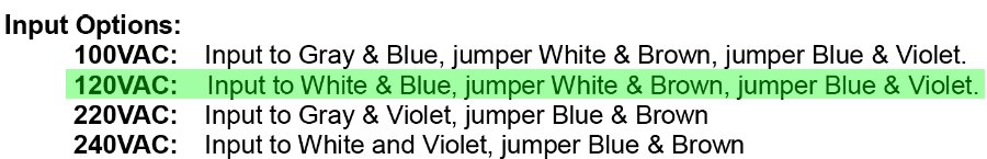
In 240V: Input to White and Violet, jumper Blue & Brown. What happens with the Grey?
Out 24V: Output from Black & Yellow, jumper Red & Orange
Does this look right?
According to the Triad toroidal
In 240V: Input to White and Violet, jumper Blue & Brown. What happens with the Grey?
Out 24V: Output from Black & Yellow, jumper Red & Orange
Does this look right?
Attachments
Dwinstonwood , I have a AT-VM95 with the conical stylus. I want to get an ML as well because it's performance is excellent with the cheap stylus.
Hey stocktrader200, I thought my VM95SH Shibata sounded amazing for the $199 price. But, it does seem like most of the people posting on various hifi forums prefer the ML MicroLine for it's clarity and detail.
I prefer a warmer sound, mainly because I listen to acoustic music, or electric music that was mic'd (which is the same thing - a mic recording acoustic sound waves in the air emanating from an amp speaker, etc.). For that reason I went with the SH.
However, after a week or so, I just wasn't loving it. So, I installed my 20yr-old Goldring 1042 and that was better, but that needle is just worn out and the cantilever had gotten loose and has no compliance (stiffness) left. I could have spent $330 on a new D42 stylus, but after 20 years of the Goldring "sound" I really wanted to try something completely new...
I just returned the VM95SH and for about $65 more I bought one of the new Grado Timbre Opus3's. As soon as it's delivered and installed I'll report back. From the reviews I'm hoping it's what I'm looking for.
In the meantime my Emerald should get fully burned in.
If you buy an ML stylus let us know what you think!
Last edited:
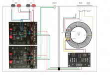
I decided to go with an all-in-one box instead but I'm not sure about the wiring.
According to the Triad toroidal
In 240V: Input to White and Violet, jumper Blue & Brown. What happens with the Grey?
Out 24V: Output from Black & Yellow, jumper Red & Orange
Does this look right?
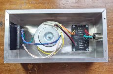
KeLLoGsX, I see one serious error: The Green/Yellow wire from the transformer is a ground wire for shielding in the transformer. Do not connect this to the Earth Ground terminal on the power receptacle. Connect it to the chassis.
You must have an Earth Ground wire from the power receptacle to the chassis. I drilled a hole in my chassis used a dedicated bolt. You could also attach the Green/Yellow transformer shield wire to this same bolt, too.
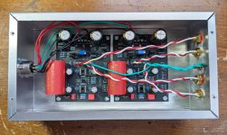
But, in your drawing there is no connection from the incoming power cable ground wire to the chassis. It's very important to have that using a very secure connection which is why I used a bolt. Look just to the left of my transformer in the pic below. You'll see a green wire running from the power receptacle to a #8 bolt:
Attachments
@dwinstonwood;
Ok, so a ground from power inlet to chassi. As well as the ground from transformer to chassi.
Got it, thanx! 🙂
You have also connected the jumpers (Blue and Brown ”pink”) with the others. Is that the way it goes. I thought I’d stick them together and leave unconnected.
Ok, so a ground from power inlet to chassi. As well as the ground from transformer to chassi.
Got it, thanx! 🙂
You have also connected the jumpers (Blue and Brown ”pink”) with the others. Is that the way it goes. I thought I’d stick them together and leave unconnected.
...You have also connected the jumpers (Blue and Brown ”pink”) with the others. Is that the way it goes. I thought I’d stick them together and leave unconnected.
I'm wired for 120VAC. I had to ask Richard about this to be clear. But, for 120VAC it's White and Brown twisted together and Blue and Violet twisted together. I attached the White/Brown pair to Line and the Blue/Violet to Neutral. And, of course, a separate Green wire from Ground to the chassis bolt. I insulated the Gray wire and tucked it away; same with the Green/Yellow shield wire (which I could have connected to the #8 chassis bolt).
Attachments
Last edited:
I decided to go with an all-in-one box instead but I'm not sure about the wiring.
According to the Triad toroidal
In 240V: Input to White and Violet, jumper Blue & Brown. What happens with the Grey?
Out 24V: Output from Black & Yellow, jumper Red & Orange
Does this look right?
Your diagram for the output is correct, it connects as two independent 12 V secondaries, one to each diode bridge on the DBRB.
The 240V AC connection is correct. Connect BLU BRN, grey is not used.
The screen connection is incorrect. It connects to the chassis. The Earth of the IEC socket also connect to the chassis (use a solid bolt with serrated washer, make sure it is to bare metal not paint). So while its true that the shield and socket are connected, the connection is not direct like you show it there.
Attachments

Last edited:
I insulated the Gray wire and tucked it away; same with the Green/Yellow shield wire (which I could have connected to the #8 chassis bolt).
No no, the shield (electrostatic screen, actually) must be connected to the chassis and earth/ground. It serves no useful purpose otherwise.
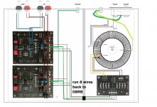
Oops, spotted another mistake. The Emerald power input is v++, com, com, v--. For convenience, duplicate COM connections are provided. The DBRB output is (+ -) (+ -). Each pair is separate.
The connection needs to be
+ -> V++
- -> com
+ -> com
- -> V--
Both inner wires of the DBRB output (+ and - maked "com") have to connect back to the Emerald COM.
You can jumper the pads at the DBRB side and use one wire to connect to one of the COM, or you can run separate wired back to the two Emerald COM pads and they will join there automatically. What you can't do is have the com of one channel connect to the + terminal of the DBRB, and com of the other channel connect to the - terminal. Even though technically both channels are at the same potential, it will likely cause problems.
Attachments
- Home
- Source & Line
- Analogue Source
- RJM Audio Emerald Phono Stage Help Desk