The wiring diagram shown in post 577 is correct. The voltages at the op amps may be a little less than 10 V, though with R20,21 at 10k ohms this is a little surprising.
What is the voltage measured at V++ and V--?
So I've rewired as per the diagram in post 577. I'm now getting +/- 12.65V on one board, and +/- 12.05V on the other. Should I be concerned about them not matching?
Hey jagdesign I reckon you are on the right track.
Thanks a lot, boss.
Hi Matt,
Yeah, you'll want to keep the COM wires off the PSU chassis, just wire to COM pads of the boards.
RM
Thanks a lot, boss.
You nailed me twice here, I used parts that have been laying around for a while, knowing that one day they might find some use. Not for this I think they are not good parts. I believe there’s an original Naim socket in there too from the Naim days.. will take some further pics for you 😉I really like you are recycling a Parallel-Printer switch-box for the power supply case !
...and those Dins...look like the classic Naim NAP/NAC locking connectors ??
Thanks Geo, I've fired it up and all seems to be working. I had to tie the grounds together at the input selector, switching them was not a good idea.
However, I'm now faced with is some faint (mains I guess) hum when I have the phono stage input connected to the output, and when the stage is powered - it stops entirely with the power off. The hum is the same level regardless of where I have the volume control (stepped attenuator).
When I switch to the DAC input or the the unused one, the hum disappears. This is with no DAC connected.
I've tried moving the Switchboard and both input selector and stepped attenuator away from the toroidal, but the noise is still there 🙁
"The hum is the same level regardless of where I have the volume control (stepped attenuator)."
That tells you it isn't from the Emerald, but after the volume control, which is strange.
That tells you it isn't from the Emerald, but after the volume control, which is strange.
Ok, this is interesting, and I should've done this sooner. I've just plugged my old EAR 834P in - straight into my Neumann KH310 active speakers, and exactly the same hum, only present when the unit is powered on.
So that's a relief that the Emerald build is hopefully ok - there is zero hiss as I wind the volume up, whereas the valve based 834P has quite a bit!
I wonder if it's something to do with the cables I'm using into the speakers? They are RCA at the pre amp end, XLR at the speaker end. Just seems odd that it only appears when the pre is powered on?
Hmmm, plugged the EAR back in, think I was getting a little hopeful - the hum definitely isn't as bad as the Emerald at the moment.
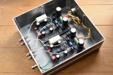
This is how it's looking with the revised power supply wiring. Since I took this photo, I've also connected both the GND points on the Emerald boards to the same chassis ground that the mains Earth is connected to - as per post 571. Unfortunately, that doesn't seem to have made any difference to the hum.

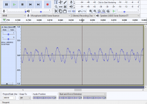
I made a recording of the hum, with my phone right up against one of the speakers. New Recording 2.m4a - Google Drive
As I say, that's what it's like with the stepped attenuator all the way down, and it doesn't really change until it's run nearly wide open. As soon as I switch power off, or switch to another input (with the power still on), the hum completely disappears.
I'm wondering if I have the stepped attenuator wired incorrectly? Currently, I have the Emerald OUT+ to IN, OUT- to GND then Goldpoint OUT and the same GND to separate pins on the input selector.
I've tried moving the Switchboard, Input Selector and Stepped Attenuator towards the rear (away from the toroidal), but couldn't hear any difference.
This is how it's looking with the revised power supply wiring. Since I took this photo, I've also connected both the GND points on the Emerald boards to the same chassis ground that the mains Earth is connected to - as per post 571. Unfortunately, that doesn't seem to have made any difference to the hum.
I made a recording of the hum, with my phone right up against one of the speakers. New Recording 2.m4a - Google Drive
As I say, that's what it's like with the stepped attenuator all the way down, and it doesn't really change until it's run nearly wide open. As soon as I switch power off, or switch to another input (with the power still on), the hum completely disappears.
I'm wondering if I have the stepped attenuator wired incorrectly? Currently, I have the Emerald OUT+ to IN, OUT- to GND then Goldpoint OUT and the same GND to separate pins on the input selector.
I've tried moving the Switchboard, Input Selector and Stepped Attenuator towards the rear (away from the toroidal), but couldn't hear any difference.
What's the resistance of the Goldpoint?
Lack of immunity to noise pickup is one of the disadvantages of a passive pre.
That said, it would have expected the noise to depend on the volume position That it doesn't is a bit of a puzzle.
What about if you disconnect the Emerald boards from V++/V-- but still have the power supply powered up?
How about if you disconnect AC earth from chassis?
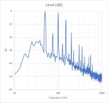
The noise is predominantly 100 Hz, i.e. rectified AC, but doesn't look much like the ripple normally seen on the Emerald power supply.
So I suspect a ground loop, and that what you are looking at here it are noise currents sourced from outside the Emerald chassis.
So I suspect a ground loop, and that what you are looking at here it are noise currents sourced from outside the Emerald chassis.
Attachments
looking at the picture it seems the boards are sitting on a different (Plastic ? white vs the aluminium of the back plate and power supply) substrate to the rest of the case and there are no ground connections to the boards out. ??
The input ground attaches to the back plate but does this connect well to the chassis and power supply stage ??
https://www.diyaudio.com/forums/att...phono-stage-help-desk-2021-10-17-00-59-50-jpg
The input ground attaches to the back plate but does this connect well to the chassis and power supply stage ??
https://www.diyaudio.com/forums/att...phono-stage-help-desk-2021-10-17-00-59-50-jpg
Last edited:
Thanks for the thoughts guys, much appreciated.
@rjm
- The Goldpoint is 50k
- With V++/V-- disconnected, and power on, the noise is gone.
- Tried removing the mains earth, but keeping the board grounds in place, and couldn't perceive any difference. I guess I could try removing the board grounds from the case as well?
@DRONE7
Well spotted, the base holding the aluminium extrusions together is some ACP (aluminium composite panel) which I had leftover. It's 0.3mm thick aluminium laminated to a polyethylene core.
As there are multiple machine screws bolting through the constituent parts, so good continuity is achieved across the complete assembly.
There are no power supply earthing points (the toroidal doesn't have a screen) other than the incoming mains earth. Or at least, that's how I have it right now.
" With V++/V-- disconnected, and power on, the noise is gone."
That's a critical clue...
Leaving V++ and V-- disconnected but reconnecting COM to the power supply, does the hum come back?
Do the GND pads on the board connect to the chassis?
That's a critical clue...
Leaving V++ and V-- disconnected but reconnecting COM to the power supply, does the hum come back?
Do the GND pads on the board connect to the chassis?
The COM connections were still connected in the previous test where the noise was gone.
GND pads on the board were connected to the chassis in this test, along with the mains earth connection.
GND pads on the board were connected to the chassis in this test, along with the mains earth connection.
Bizarre.
Alright then, since when the volume is all the way down the Emerald output signal past the pot is zero, the noise must be coupling from the Emerald power supply, into the output signal lines at or after the pot...
Alright then, since when the volume is all the way down the Emerald output signal past the pot is zero, the noise must be coupling from the Emerald power supply, into the output signal lines at or after the pot...
Bizarre indeed.
Even if the coupling were after the pot, it seems odd that it would completely go when I switch to the other inputs, especially given the input selector sits directly over the other DC lines? I'll try moving the associated attenuator wiring further back again.
Here's a better pic of everything right now.
I just tried moving the attenuator wiring away from the DC lines - I can't hear any change - a real head scratcher, this one!
Could I have damaged something when I had the rectifiers wired incorrectly previously?
Could I have damaged something when I had the rectifiers wired incorrectly previously?
Try connecting just the R and just the L Emerald boards.
In another test, try wiring a 2k2 resistor between V++ and COM, and V-- and COM, rather than connecting the boards. This will cause the power supply to operate in the same way as it does with the boards connected, but without physically routing currents through the boards.
I don't think you damaged the boards, but I suppose its possible. If it was damaged, the noise would be on the output of the Emerald, so it would get really loud if you turned up the Goldpoint.
Last edited:
Ok, so I tried the following:
- disconnected the V++/V-- from the R board, but left the COM in = hum still in both channels
- same as above for L board = hum in both channels
- then I removed the COM connection as well from the L board = no hum!
So does this mean there's an issue with the COM loop?
I started another thread on pinkfishmedia RJM Emerald Phono Pre Build | pink fish media just to get some additional thoughts, and one member mentioned the spacing between the rectifiers and length of the COM loop was not ideal.
That's progress.
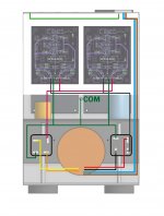
What I suggest is you disconnect the GND pad of each board from the chassis, and connect COM back to the chassis instead, tapped at some point where both channels share a common wire.
As for wiring, please see the attached image, which shows my most recent Emerald build.
What I suggest is you disconnect the GND pad of each board from the chassis, and connect COM back to the chassis instead, tapped at some point where both channels share a common wire.
As for wiring, please see the attached image, which shows my most recent Emerald build.
Attachments
Last edited:
I just tried detaching the board grounds from the chassis, but connecting a wire to the spare COM terminals on the Left board and touching the chassis at the other end. It didn’t seem to make a difference - I’m guessing ‘tapping’ point between where the COM wire splits is critical?
It shouldn't matter, as long as it's COM (i.e. behind the Emerald circuit).
But I'm confused. You reported that simply connecting COM to both Emerald boards induced hum, but connecting to a single board was silent, even with both boards powered down. That second connection should change nothing ... but if it does it could only be, I would have thought, because each board is separately connected to chassis (and earth) through the GND pad. If COM is earthed, and the boards are floating and isolated from each other, I cannot imagine how any kind of ground loop is induced by connecting COM to the second board.
For the sake of completeness however, I recommend connecting COM to chassis as soon after the rectifiers as possible.**
(** not general advice, but for troubleshooting here where GND connection on the boards is not being used)
Last edited:
- Home
- Source & Line
- Analogue Source
- RJM Audio Emerald Phono Stage Help Desk