@jagdesign
There's a lot going wrong there.
First off, you're trying to connect the Switchboard to the Emerald output for some reason, rather than between the phono in and the Emerald input.
Then there's the issue of trying to build a preamp with no preamplifier. You've added a volume control and input switch, but no voltage gain. It's a "passive preamplifier" with all the disadvantages that design choice entails.
Lastly, your return (COM) connections are pretty messed up. All RCA inputs should be floating off the chassis, the shield connection returns to the IN- connection on the boards, or the common pin of the input select.
Still, you have the basic idea.
(Phono input -> switchboard / Line input) -> rotary switch -> volume control -> [missing preamplifier board] -> output
I strongly recommend you build the emerald as a standalone phono pre, and make a separate passive switch/volume unit in it's own case you can modify/upgrade to active line pre afterwards.
Last edited:
Hi Richard, thanks for your feedback.
I now see why I’ve got confused with the switchboard connection to the output rather than input - I’ve tried loading plus between my SUT and current EAR 834P phono, on the output of the SUT, but clearly (now) they are on the input of the phono stage!
As you point out, this is just a passive preamp as I’m running the phono stage and my DAC directly into my active speakers. I appreciate the debate between active vs passive, but I have been pleased with the direct phono stage with volume control (passive) approach in previous setups - my interconnects to the speakers are 2.5m. The input selector just switches in the DAC, with it’s own pre-amp.
I’ll redraw the schematic with the revised switchboard location and my interpretation of your comments on the COM and IN- connections.
Thanks again for your help.
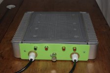
Emerald build in new case....
Awaiting Mundorf M-Cap Supreme and some better RCA connectors but tomorrow ready to trial ....
Lol... you can see where these cases came from... 'Intel ATOM '
an old custom CD-Ripper 2 box set-up called "RIP-NAS" (What else) and given all the heat-sinks there only one was used and even that had only one device on it so way overrated... I don't mind then not using the heat-sinks at all.... Just for looks and wow 🙂
(note the Emerald coloured back plate.....Lol)
As a retired (mostly) Jeweller I was firstly attracted to the RJM boards because of the naming !! DIAMOND buffer, SAPPHIRE headphone amp, EMERALD phono stage, and I have not been disappointed...they are all absolute jewels.... (very happy user ! )
Bob
Attachments

Last edited:
Ok, so I've updated the schematic.
- Switchboard moved between Phono input and Emerald boards
- Emerald outputs connected to Vol control (Emerald 'Out -' connected to Vol control 'GND', is this right?)
- Vol control ground also connected to input selector (C2)
- RCA connectors floating from chassis
Do I just need to connect the grounding post on the rear panel to the Emerald 'GND' connections, and presumably the IEC inlet Earth?
@jagdesign
As shown, the volume control is only active for the Emerald, the DAC input bypasses it. This is a poor design choice, since a user will expect the volume control to work all the time, and will be confused if the volume control suddenly stops working when the inputs are changed. However, for personal use it's OK of course.
Thinking about it, your comment that the DAC is directly connected to the active speakers makes more sense now. I suppose your DAC must have it's own volume control so there's no need to route the signal through the passive pre. In an ideal world your DAC would also have a set of line inputs you could connect the Emerald to, and you wouldn't have to fuss around with any of this.
Emerald build in new case...
Those are pretty nice heatsinks for a PC case. Pity you don't need to make use of them with the Emerald phono stage, but they look great anyway!
Hi Richard,
Yes, this is very much a bespoke design for my circumstances, my DAC (an RME ADI-2) has it's own (remote controlled) volume control which I would like to retain, so didn't want the stepped attenuator in the chain. Therefore the requirements for this 'box' are:
- Allow switching between phono and DAC
- Allow volume control of phono output
Do the ground connections look ok? Do I just need to connect the mains earth to the ground post, and if necessary, TT ground wire (currently don't have a ground wire on my tonearm) to the ground post?
Last edited:
Those are pretty nice heatsinks for a PC case. Pity you don't need to make use of them with the Emerald phono stage, but they look great anyway!
Yes and looking at them they were a re-purpose from some other build before the RIP-NAS crowd got them so I feel good to have given them a '3rd life'/up-cycle !
Oh...and at $2.50 US used each they beat the heck out of Hammond boxes !
https://www.diyaudio.com/forums/att...ld-phono-stage-help-desk-_igp2032-800x800-jpg
https://www.diyaudio.com/forums/att...ld-phono-stage-help-desk-_igp2045-800x800-jpg
Last edited:
Do the ground connections look ok? Do I just need to connect the mains earth to the ground post, and if necessary, TT ground wire (currently don't have a ground wire on my tonearm) to the ground post?
For the signal connections you have drawn in there, they are correct as shown (as best I can tell). All the returns string along the signal path, nothing connects to the chassis.
This box doesn't contain the power supply, right? If that's the case the TT ground connects to the chassis lug, the mains earth shouldn't have to.
It does contain the power supply, (and so earth connection) in the front section as shown below 
Right, ok, I see now.
So AC earth to case, then. The center tap of the transformer spits into a Y and connects to COM of both boards. Board GND to case. Input and output signal to the IN- and OUT- pads, respectively.
So AC earth to case, then. The center tap of the transformer spits into a Y and connects to COM of both boards. Board GND to case. Input and output signal to the IN- and OUT- pads, respectively.
Hey guys,
here is my take on the Emerald.
So far I have been slowly advancing in the two boxes layout, I will be using the boards from @rehanabid (thanks a lot MRA! and of course thanks to Richard @rjm for this great project and support) with Susumu RG smd resistors, output cap is 1uF which should be big enough for my 300K input impedance preamp, will be using 15-0-15V transformer (as the 12-0-12V is actually too big for the psu case (auch), but I have been able to add some 5x470uF psu caps per rail) and therefore I will be using 12K R20&R21 resistors for a bit of hotrodding/higher voltage as previously posted in this thread.
Red boards are input switches for the loading, I will be using them to optimize/set up my one and only MM cartridge.
I had available a 4pin din connector/cable from the psu to the amp boards, so I could use 4 wires for the psu; I wonder whether it would be best to keep the +21VDC and -21VDC psu voltages floating in the psu and have them (properly) connected at each COM psu input board points, what say you?
Really looking forward to having this completed, listen to it and compare it to my diy 2xECC83 phono amp.
You stay safe,
Matt.
Attachments

I managed to finish the wiring and have just powered it up. With the +/- probe points even using R22, I'm getting +/- 9.45V, which doesn't seem right given the notes specify 12-13V?
I'm using this 30VA 2x12V transformer RS PRO 230V ac, 2 x 12V ac Toroidal Transformer, 30VA 2 Output | RS Components
And these bridge rectifiers
Vishay GBPC2502-E4/51, Bridge Rectifier, 25A 200V, 4-Pin GBPC | RS Components
The voltage at the bridge rectifier outputs is 19.3V.
The voltage across IN+/- and OUT+/- for both boards is 0V.
The op amps were plugged in as per the build notes before I took these readings. Any help gratefully received!
I managed to finish the wiring and have just powered it up. With the +/- probe points even using R22, I'm getting +/- 9.45V, which doesn't seem right given the notes specify 12-13V?
I'm using this 30VA 2x12V transformer https://uk.rs-online.com/web/p/toroidal-transformers/1234013/
And these bridge rectifiers
Vishay GBPC2502-E4/51, Bridge Rectifier, 25A 200V, 4-Pin GBPC | RS Components
The voltage at the bridge rectifier outputs is 19.3V.
The voltage across IN+/- and OUT+/- for both boards is 0V.
The op amps were plugged in as per the build notes before I took these readings. Any help gratefully received!
View attachment 990541
This is how I currently have the bridge rectifier outputs connected to the Emerald boards. The toroidal has no centre tap.

I can see based on the build note diagram that this isn't right, but I'm not sure how this diagram (with one transformer, and 2 bridge rectifiers) applies to 2 Emerald boards?

Hope I haven't done any damage by connecting as per my diagram above?😕
I can see based on the build note diagram that this isn't right, but I'm not sure how this diagram (with one transformer, and 2 bridge rectifiers) applies to 2 Emerald boards?
Hope I haven't done any damage by connecting as per my diagram above?😕
Probably getting ahead of myself, but this is my interpretation of the diagram above, from the RJM site

The wiring diagram shown in post 577 is correct. The voltages at the op amps may be a little less than 10 V, though with R20,21 at 10k ohms this is a little surprising.
What is the voltage measured at V++ and V--?
What is the voltage measured at V++ and V--?
Last edited:
I wonder whether it would be best to keep the +21VDC and -21VDC psu voltages floating in the psu and have them (properly) connected at each COM psu input board points-
Hi Matt,
Yeah, you'll want to keep the COM wires off the PSU chassis, just wire to COM pads of the boards.
RM
Hey guys,
here is my take on the Emerald.
Matt.
I really like you are recycling a Parallel-Printer switch-box for the power supply case !
...and those Dins...look like the classic Naim NAP/NAC locking connectors ??
- Home
- Source & Line
- Analogue Source
- RJM Audio Emerald Phono Stage Help Desk