This is certainly the case if your 'floating' PS is 'conventional mains powered'.Try to make a floating power supply out of the same parts as a ground referred power supply, it will certainly be worse, at least in the hum performance.
But I was referring to your SolarCell/LED floating power supply. Capacitive coupling between the mains across its galvanic isolation to the floating supply is entirely within your control via the PCB layout.
Did you have hum problems with #375? The posts on this thread on the subject are unclear.
Could someone with a Gerber reader post pics of the #375 PCB layers?
The Duraglit tin is perhaps the most simple & effective solution to hum shielding. It doesn't do anything for layout deficiencies.Since you are into simplicity before anything else, with fitting in a Duraglit can as a performance metric.
In my original document, I say,
"If no such a beast is attractive enough for you, avoid ferrous enclosures entirely. An all Aluminium case doesn’t provide any protection from hum fields but at least the non-overlapping edges won’t concentrate the hum flux in unwanted places like a ferrous box with edges."
I see you use only Aluminium cases for your HPS designs.
There is a good argument for building the circuit in a Duraglit tin and hiding it in a fancy Aluminium case like those used in the HPSs. 🙂
The Duraglit tin is required for 2 x C cells. A SolarCell/LED version might fit in the traditional Altoids tin though mounting the sockets could be a problem. I have no experience of Altoids as these rebel colonial products haven't reached us loyal colonials in Cooktown.
Bill, have you received syn08's PCBs? Will they fit in the can under your pickup arm with maybe 3 x Neutrik mini XLRs? Or maybe a single 6p mini XLR?
Last edited:
No. Any duragliting is behind an already mountainous backlog. But eyeballing the picture the answer is no. The SME can isn't very big.
If you type these words into the Google search box
online gerber viewer
you will get many search hits. The one that *I* happen to prefer, is www.pcbxprt.com because it lets me control the colors. Different folks will have different preferences, I am sure.
online gerber viewer
you will get many search hits. The one that *I* happen to prefer, is www.pcbxprt.com because it lets me control the colors. Different folks will have different preferences, I am sure.
Yes, it is 2,2MOhm in the servo. Maybe this is a bit high and I go to 1MOhm. The Opamp will be a J-Fet though so this resistor can be rather high.
If you type these words into the Google search box
online gerber viewer
you will get many search hits. .
I this case as I know someone in UK who has a board in his had easier to PM them and ask. But the can is small.
I this case as I know someone in UK who has a board in his had easier to PM them and ask. But the can is small.
Don't bother, attached is a photo of the two versions of the #375 board, one with a ground plane, one without and with the ground trace as symmetric as possible.
There is absolutely no difference in the hum between these two versions, both are equally "bad" (that is, worse than any ground referred low noise preamp I have ever built), in particular for the switching wall wart. Which tells me the hum coupling is not through the #375 ground, but through the ground connection of the instrument used to measure the noise (or the following preamp ground). This connection is effectively a poor balanced to single ended connection. IMO the only practical way to minimize this hum is to lower the transformer pri-sec parasitic capacitance, everything else is beyond the user control.
This is IMO the shortcoming of all these floating supply head amps: connecting them to the outside world is a significant problem. I can estimate some 6-10dB higher hum compared with a head amp with a ground referred power supply, with all the ground loop countermeasures implemented.
I'll try when I have the chance more connectivity solutions. The ideal solution would be an isolation opamp, build around an high speed optocoupler or wideband transformer (front side fed from the solar cell, back side fed from the following stage ground referred power supply), not a big deal, but then it breaks the illusory simplicity of these floating power supply, common base stages.
Attachments

Last edited:
You could connect a number N of transformers in series, to reduce the capacitance coupling between input (mains) and output (secondary of transformer # N).
If you also connected a capacitor of Cs farads across each secondary, it would create a capacitive voltage divider at the output of each transformer. The upper leg of the divider is the primary-to-secondary parasitic capacitance, and the lower leg is the added Cs. This divides (attenuates) capacitively coupled noise. A "pi" topology lowpass filter (CRC or CLC) between secondary and primary[i+1] would be even better.
CRC would be viable in a preamp (sub-50mA mains current) but less so in more power hungry equipment.
Last edited:
You could connect a number N of transformers in series, to reduce the capacitance coupling between input (mains) and output (secondary of transformer # N).
If you also connected a capacitor of Cs farads across each secondary, it would create a capacitive voltage divider at the output of each transformer. The upper leg of the divider is the primary-to-secondary parasitic capacitance, and the lower leg is the added Cs. This divides (attenuates) capacitively coupled noise. A "pi" topology lowpass filter (CRC or CLC) between secondary and primary[i+1] would be even better.
All good ideas, they remind me of an old joke:
-----------------------
John is struggling through a bus station with two huge and obviously heavy suitcases when a stranger walks up to him and asks "Have you got the time?"
John sighs, puts down the suitcases and glances at his wrist. "It's a quarter to six," he says.
"Hey, that's a pretty fancy watch!" exclaims the stranger. John brightens a little.
"Yeah, it's not bad. Check this out" - and he shows him a time zone display not just for every time zone in the world, but for the 86 largest metropolises.
He hits a few buttons and from somewhere on the watch a voice says "The time is eleven 'til six" in a very West Texas accent. A few more buttons and the same voice says something in Japanese. John continues "I've put in regional accents for each city". The display is unbelievably high quality and the voice is simply astounding.
The stranger is struck dumb with admiration. "That's not all", says John. He pushes a few more buttons and a tiny but very high-resolution map of New York City appears on the display. "The flashing dot shows our location by satellite positioning," explains John.
"View recede ten", John says, and the display changes to show eastern New York state.
"I want to buy this watch!" says the stranger.
"Oh, no, it's not ready for sale yet; I'm still working out the bugs", says the inventor.
"But look at this", and he proceeds to demonstrate that the watch is also a very creditable little FM radio receiver with a digital tuner, a sonar device that can measure distances up to 125 meters, a pager with thermal paper printout and, most impressive of all, the capacity for voice recordings of up to 300 standard-size books, "though I only have 32 of my favorites in there so far" says John.
"I've got to have this watch!", says the stranger.
"No, you don't understand; it's not ready -"
"I'll give you $1000 for it!"
"Oh, no, I've already spent more than -"
"I'll give you $5000 for it!"
"But it's just not -"
"I'll give you $15,000 for it!" And the stranger pulls out a checkbook.
John stops to think. He's only put about $8500 into materials and development, and with $15,000 he can make another one and have it ready for merchandising in only six months. The stranger frantically finishes writing the check and waves it in front of him. "Here it is, ready to hand to you right here and now. $15,000. Take it or leave it."
John abruptly makes his decision. "OK", he says, and peels off the watch.
They make the exchange and the stranger starts happily away. "Hey, wait a minute", calls John after the stranger, who turns around warily. John points to the two suitcases he'd been trying to wrestle through the bus station. "Don't forget your batteries".
This is IMO the shortcoming of all these floating supply head amps: connecting them to the outside world is a significant problem. I can estimate some 6-10dB higher hum compared with a head amp with a ground referred power supply, with all the ground loop countermeasures implemented.
I think I can deal with that as (if I ever complete it) I'll be battery powered to the ADC and then out optically to miniDSP. But I am a complete outlier 😀
But I am a complete outlier 😀
There is no disagreement on that.
And the colour of the suitcases?
🙂
George
Attachments

I did used to have a UPS battery I used for starting project cars when they were misbehaving. was for a telco UPS so big Ah rating. I gave it away in the end to a friend with a garage who loved it. Would have run the preamp for about 2 years, but huge, heavy and bright yellow!
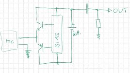
Since I'm not really good at simulation SW, I can't find an answer for myself.
With Kirchhoff in mind, I would think that just one output cap does suffice for operation, or do I overlook something?
See attached pic
Works for high capacity batteries, but not very well for solar cells, they have high output impedance. For the #375 arrangement, the solar cell short current is about 30mA, which makes for an internal impedance of about 100 ohm. Could be ok, or could be not, depends on the gain, load, etc...
What is the LED current for this performance?For the #375 arrangement, the solar cell short current is about 30mA, which makes for an internal impedance of about 100 ohm.
Densen
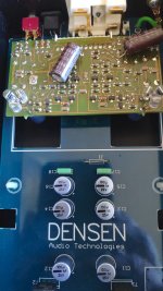
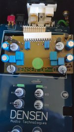
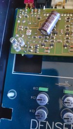
Long overdue, but as promised for Syn-08 here are some pic´s of the Densen DP-Drive with DP-02 MC board fitted. My friend complained abot the sound being very week and distorted, so he brought it for me to repair. One leaking main cap, and both LED´s shorted (they use white high bright LED´s instead of standard bulbs). I guess they´re driving them too hard, since they have been changed before.
Think you´ll need a schematic to really see, how they implemented it. Anyway... here goes....
Attachments


Last edited:
- Home
- Source & Line
- Analogue Source
- Richard Lee's Ultra low Noise MC Head Amp