keeping this effect low for MC headamps is to use floating battery supplies in a well shielded case together with the amp in very close proximity and make all the stray capacitances from the two floating power supply rails to the main system ground and to the noise/hum source as small as possible. Changing the hum level by exchanging an amp in the chain following the headamp is simply due to the fact that different amplifiers have different leakage impedances from their own ground to mains earth. Higher impedances (= smaller stray cap) means smaller hum currents in the loop.
Agreed on all counts; you and me are in violent agreement regarding the hum entry path. Just curious, where would you connect the shield in this particular floating schema? I can't find any obvious right place...
In a normal non-floating supply configuration I would connect the head amp shield to the next stage ground, but here this ground is the same as the head amp ground, which, in fact, from a hum perspective, is as "live" as the output.
Really excited to find the time to build the SYN08 version and see/hear what all the hum issues are about.
FYI this one does not hum..... at all
Densen uses this version in their DP drive in the MC board called DP-02. I gave one to one of my friends and this also doesn´t hum at all. Densen claims a S/N figure A-weighted of 80 dB for this MC board. Just wondering......
FYI this one does not hum..... at all
Densen uses this version in their DP drive in the MC board called DP-02. I gave one to one of my friends and this also doesn´t hum at all. Densen claims a S/N figure A-weighted of 80 dB for this MC board. Just wondering......
Attachments
Really excited to find the time to build the SYN08 version and see/hear what all the hum issues are about.
FYI this one does not hum..... at all
Densen uses this version in their DP drive in the MC board called DP-02. I gave one to one of my friends and this also doesn´t hum at all. Densen claims a S/N figure A-weighted of 80 dB for this MC board. Just wondering......
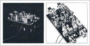
It would be interesting to find out how this Densen head amp was implemented. A photo of the inside would be enlightening... probably not going to happen.
John Curl designed a couple preamps for an outfit called Dennesen with three n's . Here's one that Google Image Search located
They are perhaps best remembered for their Soundtractor , a cartridge alighnment tool that resembles a protractor from the Geometry class that 15 year olds take in school.
They are perhaps best remembered for their Soundtractor , a cartridge alighnment tool that resembles a protractor from the Geometry class that 15 year olds take in school.
Attachments
Last edited:
Soundtractor , a cartridge alighnment tool that resembles a protractor from the Geometry class that 15 year olds take in school.
Still have one. I remember listening with Mr. D to the JC-80 trying to A/B different bypass caps, being Irish he had us "precondition" ourselves over lunch.
Have you tried an alternative wall-wart syn08?
Tried 5 models in total. Both SMPS wall warts are more or less the same, practically unusable. All 3 linear wall warts (transformer+bridge+electrolytic) are more or less the same (much better, at least one order of magnitude, than the SMPSs) but there are significant measurable differences. The best one I am currently running is a 15Vdc/600mA (18.5V @ the current LED current of about 150mA) which makes the already mentioned 100nV equivalent hum at the input.
I agree with what Andreas(?) said that the root cause for the SMPS poor behavior is the mandatory capacitive coupling (in the circuit) between the high side and the low side of the switcher. Linear wall warts do not have such capacitors added (and they don't need one).
It would be interesting to find out how this Densen head amp was implemented. A photo of the inside would be enlightening... probably not going to happen.
I probably can´t get the schematics, but I´ll be happy to take a picture of the 02 mc module next time I visit my friend 😀
In the meantime check out Dimitris link to LC audio´s riaa. That´s exactly how it´s made (smd components though) 🙂
I probably can´t get the schematics, but I´ll be happy to take a picture of the 02 mc module next time I visit my friend 😀
In the meantime check out Dimitris link to LC audio´s riaa. That´s exactly how it´s made (smd components though) 🙂
Schematic doesn't tell the whole story. My specific question is about where to connect the head amp shield.
Schematic doesn't tell the whole story. My specific question is about where to connect the head amp shield.
I´ll try to get some close up´s 🙂
Tried 5 models in total. Both SMPS wall warts are more or less the same, practically unusable. All 3 linear wall warts (transformer+bridge+electrolytic) are more or less the same (much better, at least one order of magnitude, than the SMPSs) but there are significant measurable differences. The best one I am currently running is a 15Vdc/600mA (18.5V @ the current LED current of about 150mA) which makes the already mentioned 100nV equivalent hum at the input.
I agree with what Andreas(?) said that the root cause for the SMPS poor behavior is the mandatory capacitive coupling (in the circuit) between the high side and the low side of the switcher. Linear wall warts do not have such capacitors added (and they don't need one).
When I was at NXP/Philips, I saw small SMPSU’s that coupled the mains side 0V
to the secondary side with a 1-2 nF capacitor to meet emissions standards. If you have a ground loop and HF garbage floating around, that will be going straight across the isolation barrier and getting modulated by the 50/60 Hz stuff.
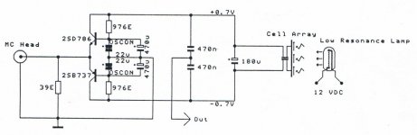
It's much more simple than thought. Simulator is your friend ... as soon as you know what to simulate. I just took a Duraglit circuit and added a metal housing and a '250Vac / 50Hz mains voltage source to simulate the LED power supply. I assumed 100 pF stray cap between mains live line and the PS secondary side, 50 pF stray cap from the LED DC power rails to the housing and another 10 pF stray cap to the floating PS + and + rails each (btw, it does'nt matter if there is an equal coupling to both rails, one is already sufficient but the effect gets a little bit less pronounced by a few dB)
What you get as output signal from the mains line is as follows:
- if housing is left floating: output is 50 Hz sine wave with 250µV amplitude (with an assumed cartridge output of 6 mV amplitude, this is only 27dB down which is not acceptable by a good margin)
- if housing is grounded to the amp (cartridge input, BJT base caps and output resistor), 50 Hz signal is going down to 170µV amplitude ... a little bit better but still far away from being good.
Why is amplitude going down? The stray cap between LED PS lines and housing creates a bypass for the hum signal (50pF > than 2x10pF)
- if I now connect an additional cap of 100 nF from the LED supply line to the housing, 50 Hz signal is going down to 240 nV. This is now at -87dB below signal !
So conclusion is:
- ground the headamp housing to the input/output ground (as Richard descibed it as the housing to be the extension of the input/output cable shield)
- add 100nF or bigger caps from any additional supply line entering the housing
Interestingly, such 100 nF caps which everybody would see as an RF filter cap is in this case an effective filter for 50/60 Hz hum. Adding a common mode choke does not hurt (it helps to suppress sum potential high frequency garbage) but for the hum, it does'nt matter.
See attached LTSpice file illustrating the above
Attachments
Last edited:
When I was at NXP/Philips, I saw small SMPSU’s that coupled the mains side 0V
to the secondary side with a 1-2 nF capacitor to meet emissions standards. If you have a ground loop and HF garbage floating around, that will be going straight across the isolation barrier and getting modulated by the 50/60 Hz stuff.
That’s exactly the cap I was mentioning. The troublemaker.
It's much more simple than thought. Simulator is your friend ... as soon as you know what to simulate. I just took a Duraglit circuit and added a metal housing and a '250Vac / 50Hz mains voltage source to simulate the LED power supply. I assumed 100 pF stray cap between mains live line and the PS secondary side, 50 pF stray cap from the LED DC power rails to the housing and another 10 pF stray cap to the floating PS + and + rails each (btw, it does'nt matter if there is an equal coupling to both rails, one is already sufficient but the effect gets a little bit less pronounced by a few dB)
What you get as output signal from the mains line is as follows:
- if housing is left floating: output is 50 Hz sine wave with 250µV amplitude (with an assumed cartridge output of 6 mV amplitude, this is only 27dB down which is not acceptable by a good margin)
- if housing is grounded to the amp (cartridge input, BJT base caps and output resistor), 50 Hz signal is going down to 170µV amplitude ... a little bit better but still far away from being good.
Why is amplitude going down? The stray cap between LED PS lines and housing creates a bypass for the hum signal (50pF > than 2x10pF)
- if I now connect an additional cap of 100 nF from the LED supply line t0 the housing, 50 Hz signal is going down to 240 nV. This is now at -87dB below signal !
So conclusion is:
- ground the headamp housing to the input/output ground (as Richard descibed it as the housing to be the extension of the input/output cable shield)
- add 100nF or bigger caps from any additional supply line entering the housing
Interstingly, such 100 nF caps which everybody would see as an RF filter cap is in this case an effective filter for 50/60 Hz hum.
See attached LTSpice file illustrating the above
I see this as a sort of Wheatstone capacitive bridge nulling. Too late for me, but others may try it. Makes sense, although I’m not entirely sure how critical the matching in the two branches is. In simulation the matching is ideal and the bridge can be conveniently nulled.
The funniest way would be to add two fixed 100n caps, then try to balance the bridge by trimming a 100pf in parallel with the parasitics.
In this case, the troublemakers are even 10 times bigger as my assumption for the sim. This also means that the stray caps between LED supply and housing and floating supply in your amp are more than 10 times lower than my assumption. In your case it seems that the noise is coming from a stray cap in the order of 1 pF!!
Fantastic, many thanks.It's much more simple than thought. Simulator is your friend ... as soon as you know what to simulate. I just took a Duraglit circuit and added a metal housing and a '250Vac / 50Hz mains voltage source to simulate the LED power supply. I assumed 100 pF stray cap between mains live line and the PS secondary side, 50 pF stray cap from the LED DC power rails to the housing and another 10 pF stray cap to the floating PS + and + rails each (btw, it does'nt matter if there is an equal coupling to both rails, one is already sufficient but the effect gets a little bit less pronounced by a few dB)
What you get as output signal from the mains line is as follows:
- if housing is left floating: output is 50 Hz sine wave with 250µV amplitude (with an assumed cartridge output of 6 mV amplitude, this is only 27dB down which is not acceptable by a good margin)
- if housing is grounded to the amp (cartridge input, BJT base caps and output resistor), 50 Hz signal is going down to 170µV amplitude ... a little bit better but still far away from being good.
Why is amplitude going down? The stray cap between LED PS lines and housing creates a bypass for the hum signal (50pF > than 2x10pF)
- if I now connect an additional cap of 100 nF from the LED supply line to the housing, 50 Hz signal is going down to 240 nV. This is now at -87dB below signal !
So conclusion is:
- ground the headamp housing to the input/output ground (as Richard descibed it as the housing to be the extension of the input/output cable shield)
- add 100nF or bigger caps from any additional supply line entering the housing
Interestingly, such 100 nF caps which everybody would see as an RF filter cap is in this case an effective filter for 50/60 Hz hum. Adding a common mode choke does not hurt (it helps to suppress sum potential high frequency garbage) but for the hum, it does'nt matter.
See attached LTSpice file illustrating the above
This is exactly what I was asking for.
Hans
I think matching is not required . The 100 nF caps are a simple bypass wich a much lower impedance than the stray caps. They bypass the internal stray cap to the floating rails and the resulting current through the output resistor. With the caps, the troublemaker hum signal flows directly from the LED supply lines into ground and not through the output resistor. And only current flowing through this resistor creates an output signal.I see this as a sort of Wheatstone capacitive bridge nulling. Too late for me, but others may try it. Makes sense, although I’m not entirely sure how critical the matching in the two branches is. In simulation the matching is ideal and the bridge can be conveniently nulled.
The funniest way would be to add two fixed 100n caps, then try to balance the bridge by trimming a 100pf in parallel with the parasitics.
If one of the stray caps is changed from 10 pF to 20 pF and the one to the other floating supply rail is eliminated, no change in output signal happens.
Here's what I simmed to try to understand the issue. Seems as Andreas mentions, you must have the metal shield and it must be connected to 0V. you can vary the capacitances over a very wide range, and the solution is quite robust (capacitances do not need to be 'balanced').
Attachments
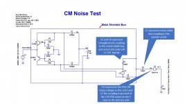
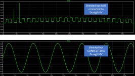
You just replaced my 100 nF cap from supply line to housing with a dead short. In reality, the 100nF and the internal strays form a simple current divider - the current through the strays ends up in the output resistor creating an output voltage and the current through the 100nF bypass cap flows directly to ground (and not through the output resistor to ground). The suppression ratio is simply the ratio between the sum of all strays into the amp circuit vs. the bypass cap value. That's all - no magic🙂Here's what I simmed to try to understand the issue. Seems as Andreas mentions, you must have the metal shield and it must be connected to 0V. you can vary the capacitances over a very wide range, and the solution is quite robust (capacitances do not need to be 'balanced').
- Home
- Source & Line
- Analogue Source
- Richard Lee's Ultra low Noise MC Head Amp