Andreas,
Obviously the trouble in your Sim is caused by the 100pF cap from the PS.
Now placing 100nF to gnd attenuates the signal from said 100pF by 60dB max depending on the value of C6 (here 50pF) , so amplitude to the Duraglit through the 10pF caps goes also down by the same amount.
But in your Sim file, the Signal Gnd is connected to the metal housing, where you seem to assume a very low impedance between signal gnd and mains gnd, so whereto is this current flowing and doesn't this cause other problems elsewhere ?
What if you connected the metal housing to the mains gnd and not to interconnect this housing with the signal gnd ?
Would this not have a better effect in attenuating the signal coming from the 100pF, because the mains gnd has a very low impedance to this 100pF signal.
Hans
yes, I assume that the signal ground is connected via a certain impedance to mains earth via the downstream amplifiers following the MC headamp (RIAA amp, linelevel preamp, powramp) which is much lower than the impedance from the stray caps. If these are mains powered there is usually a connection beteen signal ground and mains earth. Even if it is not a direct short, there are very often small resistors between signal ground and amp housing or at least some capacitors in the 100nF range or larger. Yes the resulting 50 Hz current through the ground line has the potential to create trouble somewhere else. If you connect the housing directly to mains earth, then the amp can not have any direct connection to signal ground - otherwise a major ground loop can be created. Finally it all depends on the real impedances and one must test in a setup what connection is best. Same as with your turntable - connect the tonearm to signal ground or to mains earth? If you are going fully balanced, ground does not carry any signal current and you are safe.Andreas,
Obviously the trouble in your Sim is caused by the 100pF cap from the PS.
Now placing 100nF to gnd attenuates the signal from said 100pF by 60dB max depending on the value of C6 (here 50pF) , so amplitude to the Duraglit through the 10pF caps goes also down by the same amount.
But in your Sim file, the Signal Gnd is connected to the metal housing, where you seem to assume a very low impedance between signal gnd and mains gnd, so whereto is this current flowing and doesn't this cause other problems elsewhere ?
What if you connected the metal housing to the mains gnd and not to interconnect this housing with the signal gnd ?
Would this not have a better effect in attenuating the signal coming from the 100pF, because the mains gnd has a very low impedance to this 100pF signal.
Hans
Last edited:
Yes the resulting 50 Hz current through the ground line has the potential to create trouble somewhere else.
If you connect the housing directly to mains earth, then the amp can not have any direct connection to signal ground - otherwise a major ground loop can be created.
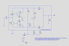
Could you please explain why this could happen.
What's wrong with the image below ?
Hans
Attachments
A Duraglit is a very nice but sensitive low noise design, should preferably be powered by batteries and is dependant on Hfe.
In your version, Hfe dependancy is eliminated, but open loop gain is very low, making this version unsuited for a wide range of Carts.
Either variant sounds like a perfect high end product! I think the list price needs to be higher 🙂
I have to say that IMO the low gain isn't a drawback for me as project 'eventual' will cope will all sorts. I am starting to think that the plan to battery power the next stage and have an A/D in there with an optical link to the miniDSP is the way to avoid madness though. Just depends if my friend ever comes good on the PCM4222 EVM he promised me...or I give up and just buy one.
You just replaced my 100 nF cap from supply line to housing with a dead short. In reality, the 100nF and the internal strays form a simple current divider - the current through the strays ends up in the output resistor creating an output voltage and the current through the 100nF bypass cap flows directly to ground (and not through the output resistor to ground). The suppression ratio is simply the ratio between the sum of all strays into the amp circuit vs. the bypass cap value. That's all - no magic🙂
Yes - agree. As long as the connection impedance from the Duraglit gnd to the metal housing shield is a few orders of magnitude lower than the other coupling paths you would be good to go.
Any thoughts on a CM ferrite clamp around the supply to the LED’s? I would expect any HF noise to be attenuated as this raises the total loop Z at HF.
Last edited:
Either variant sounds like a perfect high end product! I think the list price needs to be higher 🙂
I have to say that IMO the low gain isn't a drawback for me as project 'eventual' will cope will all sorts. I am starting to think that the plan to battery power the next stage and have an A/D in there with an optical link to the miniDSP is the way to avoid madness though. Just depends if my friend ever comes good on the PCM4222 EVM he promised me...or I give up and just buy one.
Off topic, is anybody aware of a good DAC EVM? TI is no longer doing the PCM1794, the Cirrus has something but its absurdly expensive ($700) for the performance, AKM and other nomina odiosa suspects don't seem to have any for sale, at any price.
All I see is crap DAC EVMs with -96dB distortions.
Last edited:
TO BE COMPLETED
... and you are not using the transformer/rectifiers/caps supply in #238 but have a single socket to connect either wall-wart, Mean Well or Agilent. Again where is the connection to chassis and any RF decoupling? To complete the picture, the connection and RF decoupling to chassis would be nice. Is it 2wire+shield from MCHA to MM RIAA amp?
______________________
We are too eager to blame #375 for poor performance with the Mean Well SMPS. I bet you will have similar yucky performance with any LN amp if you use the SAME EARTHING/RF DECOUPLING/CHASSIS/CONNECTION system with the Mean Well. We can test this by replicating syn08's Mean Well results, disabling the amp by eg disconnecting one or both connections to the Solar Cell, or both collectors.
In , #1231 I list 3 mechanism that allow the yucky stuff on the LED supply to cross the Galvanic isolator and appear on the output of the MCHA/input of the MM RIAA. I don't even mention the circuit except for 3. where I talk about physical positioning of RF base/emitter caps.
Our 'cure' depends on which path is dominant and 'how dominant'. So the first stage is to determine this
I also make several ASSumptions and perhaps it might be wise to re-examine these
Could you do the same for #375 please. I take it you are using 2wire+shield from cartridge to MCHA as #238. Where, if any, is the RF decoupling to chassis?Schematic doesn't tell the whole story. My specific question is about where to connect the head amp shield.
... and you are not using the transformer/rectifiers/caps supply in #238 but have a single socket to connect either wall-wart, Mean Well or Agilent. Again where is the connection to chassis and any RF decoupling? To complete the picture, the connection and RF decoupling to chassis would be nice. Is it 2wire+shield from MCHA to MM RIAA amp?
______________________
We are too eager to blame #375 for poor performance with the Mean Well SMPS. I bet you will have similar yucky performance with any LN amp if you use the SAME EARTHING/RF DECOUPLING/CHASSIS/CONNECTION system with the Mean Well. We can test this by replicating syn08's Mean Well results, disabling the amp by eg disconnecting one or both connections to the Solar Cell, or both collectors.
In , #1231 I list 3 mechanism that allow the yucky stuff on the LED supply to cross the Galvanic isolator and appear on the output of the MCHA/input of the MM RIAA. I don't even mention the circuit except for 3. where I talk about physical positioning of RF base/emitter caps.
Our 'cure' depends on which path is dominant and 'how dominant'. So the first stage is to determine this
I also make several ASSumptions and perhaps it might be wise to re-examine these
- Across the LED/Solar Cell via poorly laid out PCB with a lot of capacitance across this Galvanic Isolator. I don't believe syn08 would make such a newbie mistake. syn08, does #375 PCB have an earth plane and is this shared between the amp-with-floating-supply .. and the LED supply? If so, the capacitive coupling across the Galvanic Isolator would be 10x or greater.
- We still haven't rulled out classic hum loop / XLR pin 1 problem bla bla. The detailed earthing/chassis/decoupling/wiring diagram for the cartridge-MCHA-MM RIAA amp chain would probably suffice for those versed in the art.
- Don't rule out RF rectification of stuff on the mains of SMPS often appears like mains hum/buzz. You get it even with charging currents on conventional PSUs) On the integrated amp with powered Duraglit, the little RF 'oscillations' at rectifier off in the conventional transformer/rectifiers/caps PSU could be heard on the MC input. The 'white' noise hiss was lower than any other product at that time so the 'hum' buzz was apparent though it measured less than the hiss. Solved by special diodes, re-routing mains wiring and RF suppression caps across the diodes and other parts of the PSU
-
Last edited:
Nothing is wrong with your circuit. I said if you now also connect the housing to signal ground, then we will have the potential to create a classic ground loop via the signal ground to the downstream amplifiers.Could you please explain why this could happen.
What's wrong with the image below ?
Hans
As I already wrote - an additional CM choke aka ferrite clamp will help to reduce potential additional RF crud entering the amp from the LED supply.Yes - agree. As long as the connection impedance from the Duraglit gnd to the metal housing shield is a few orders of magnitude lower than the other coupling paths you would be good to go.
Any thoughts on a CM ferrite clamp around the supply to the LED’s? I would expect any HF noise to be attenuated as this raises the total loop Z at HF.
4. TIMEOUT DAMMIT! . cont'd from #1267
Hans & Bill, Yes a differential MM RIAA simplifies dealing with these issues but you don't need differential Duraglit if you keep it floating and 2wire+shield all the way to the cartridge. In fact, Duraglit floating, 2wire+shield from MM all the way to the cartridge with SE MM RIAA gives you 90% of the benefit of differential MM RIAA.
_____________
I don't think any of us would use a Mean Well or wall-wart SMPS for a stand alone LN amp by choice but it is certainly possible to do so with a lot of attention to detail.
syn08 has shown we can get at least an order of magnitude better using simple transformer/rectifier/cap wall-wart and I don't think we need to go to Agilent to power the LEDs for exemplerary noise performance.
If integrated with the MM RIAA, things are much simplified as we have the earthing/chassis/connection/RF decoupling under out control though we still need to be wary of inadvertent RF flying around inside the chassis .. eg the rectifier spikes. Powering the LEDs with an existing regulated rail is probably sufficient
________________
I think Hans, aboos, Bonsai & I are slowly converging to a common solution for very LN. We are probably at the stage where we need solder to find the best solution for a particular case so I won't pontificate on specifics.
But if I may state some important principles ..
- Shields should not carry signal .. ie shouldn't act as grounds. Their sole purpose is to act as shields.
- We decouple to shields to reduce the yucky stuff on lines we are decoupling. eg we decouple the +ve & -ve lines of the LED psu WHERE THEY ENTER THE CASE so the mains hum & buzz and RFI 'hum' & buzz on those lines are reduced.
- The shield/chassis is LoZ to perform this function
- You don't decouple to signal earth cos then the yucky stuff is indistinguishable from signal and is AMPLIFIED BY SUBSEQUENT AMPLIFIERS
- Usually, the coupling between shield and signal earth is small enough to avoid signal earth contamination from yucky stuff on the shield
- If we are lucky, any contamination from shield to signal earth is also on signal 'hot' and hence rejected by the subsequent amp. Differential input amps capitalize on this. As does correct 2wire+shield wiring.
- Beware of RF penetrating the chassis via any lines including the shields of cables. 2" is enough to render decoupling caps & inductors useless for RF rejection.
Nothing is wrong with your circuit. I said if you now also connect the housing to signal ground, then we will have the potential to create a classic ground loop via the signal ground to the downstream amplifiers.
So this means the best solution in case of using a wall wart is:
1) Metal housing connected to mains gnd but no further connection to the signal gnd to prevent gnd loops
2) At the entry of the PS lines two 100nF caps to the metal housing to attenuate the CM pollution from the Wall Wart.
3) Possibly as an extra suppression of diff pollution a 100nF cap between both PS lines at the entry of the metal box and/or ferrite chokes in the wall wart line
Is this a correct recap of the above discussion ?
Hans
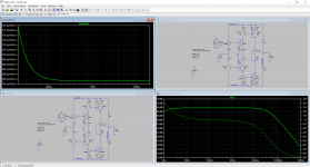
Full agreement... my sim was not intended to show the one and only way to eliminate the hum but to demonstrate the basics and the way the hum is introduced into the system.
IN addition to your 3 points, make shure that all grounding connections of all equipment in the audio chain to mains earth are ending up in one point at the same power outlet to ensure that there are no residual voltage differences left between the grounding points.
IN addition to your 3 points, make shure that all grounding connections of all equipment in the audio chain to mains earth are ending up in one point at the same power outlet to ensure that there are no residual voltage differences left between the grounding points.
Last edited:
I see this as a sort of Wheatstone capacitive bridge nulling. Too late for me, but others may try it. Makes sense, although I’m not entirely sure how critical the matching in the two branches is. In simulation the matching is ideal and the bridge can be conveniently nulled.
The funniest way would be to add two fixed 100n caps, then try to balance the bridge by trimming a 100pf in parallel with the parasitics.
But if you connect your housing ie shield to the Duraglit 0V directly or through a suitably large cap surely that will solve your problem? I assume the capacitive coupling from the LED side to the solar cell is only a 100 pF or so max and probably a good deal lower. I would not of course earth/ground the box because the. You have an earth loop problem.
So this means the best solution in case of using a wall wart is:
1) Metal housing connected to mains gnd but no further connection to the signal gnd to prevent gnd loops
2) At the entry of the PS lines two 100nF caps to the metal housing to attenuate the CM pollution from the Wall Wart.
3) Possibly as an extra suppression of diff pollution a 100nF cap between both PS lines at the entry of the metal box and/or ferrite chokes in the wall wart line
Is this a correct recap of the above discussion ?
Hans
I would have thought the correct approach is to connect the shield (is metal box) to the Duraglit 0V directly or through a large cap but do not earth the box.
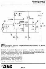
those zetex transistors are more like MJ15031,32 stuffed into a TO92 package.
200v 5A continuous 20A peak. this thing should be in a TO-220 package and used for outputs.
200v 5A continuous 20A peak. this thing should be in a TO-220 package and used for outputs.
You may not realize that Zetex's competitive advantage is that they allow you to run their plastic packaged "E Line" transistors at 200 deg C junction temperature. So they can permit greater current and greater power than, oh shall we say, unaggressive competitors.
- Home
- Source & Line
- Analogue Source
- Richard Lee's Ultra low Noise MC Head Amp