bonsai said:If you are using a wall-wart to power up an LED<>solar-cell array to provide a isolation in the syn08 Duraglit, surely its just easier to regulate the wall-wart down and feed the Duraglit directly since the wall-wart output is already floating?
Yes.In the Duraglit the floating power supply is moving up and down with respect to ground carrying the full output signal. So haveing quite a distance makes the complete structure huge and hum and other interference is likely. For such lowest noise amps with floating supply systems, power supply and amp shold be very close with as short as possible leads in between and the complete structure should be shielded. Therefore having batteries or solar cell power supplies on board is ideal.
The PSU is floating & connected directly to the output. This would only work if you could connect your PSU (2 in anti-phase) directly to the input of your MM stage and get no mains sh*t. 😀
The wiring & layout issues I mention in my document, transformer capacitances, the stuff that aboos points ... out all bear on this. The wall-wart isn't fully isolated/floating. It is connected to the outside world by the wiring/layout/capacitances etc. and you are sticking all of this on your MM input.
Not quite. Duraglit isn't balanced. It's always been 'single ended'. But importantly, the PSU is floating.After looking closer (I will be back with a throughout analysis) I'm afraid that in the general case connecting these floating ground schematics to the outside world is more complicated than it appears at the first sight ..... Reason is, connecting the Duraglit to the outside world makes implicit conversion from balanced to single ended (ground referred).
This is what the Battery or Solar Cell power is meant to provide, uncontaminated by other connections/wiring/layout/capacitances etc
I would check the PCB for capacitance between the LED powering and the Solar Cell / signal side
I'm almost certain your issues with the Mean Well are due to hum loop issues. Do you still have yucky stuff when you disable #375 eg by cutting the connections on the solar cell?
Are you using the good methods/practices you showed earlier to connect long unbalanced lines, right up to the PCB and to the MM stage?
My original document is quite pedantic about how this is maintained both in battery Duraglit as well as the powered Newton version
But your wall-wart version is already proof that it is possible.!!! 😱syn08 said:So this sad conclusion makes the whole floating Duraglit concept more of an academic interest. It is an interesting minimalistic concept/exercise, but I'm afraid it is not ideal for integrating, from a system perspective
This implies that eg in an integrated product, upgraded normal +/- 15V supplies to drive the LED 50mA will do the job.
Sorry, with all respect, there’s no way I understand what you are trying to explain.The whole Duraglit supply is being dragged up an down by the common mode voltage that is arising between the mains 0V and the circuit. Te wall-wart switching mosfet drain is swinging probably to 500 or 600 Volts peak wrt ground and its capacitively coupled through the transformer to the secondary side. The result will be some Volts of HF noise with 100/120 Hz ripple superimposed on it. In the sim I used 100pF to each side of the solar cell, but even with just 10pF to each side, 10V pk-pk common mode noise still gives you 3-5 mV of noise at Vout. You can connect the LED supply + or - directly to the Duraglit ground and it blocks the CM noise problem, but you then have ground loops to worry about.
So, it seems the operating requirements
1. maintain very low non-signal related CM noise across the battery (solar cell)
2. keep any extraneous capacitive coupled noise to the transistor collectors to a minimum (low single digit pF)
3. keep the power supply and the circuit compact and of course shield it (same comment as Andreas made)
4. absolutely make sure there is no common mode noise between the amplifier ground and the floating power supply
(NB - One option to try might be a suitable ferrite CM clamp core around wire from the wall-wart to the LED's)
What is a CM signal between the mains 0 volt and the circuit that you refer to ?
The SMPS is powering LED’s, that’s it. I see no harm whatsoever when the Led’s are floating up and down as long as the produce a constant light output.
Or is the light output modulated by 60 Hz ?
Nothing here is connected to the Duraglit other than optically.
As a matter of fact, is the metal casing connected to mains gnd, just as the chassis of the TT and the amp following the Duraglit should be or do we have some ground loop causing hum.
I really need a model to understand what’s happening.
Hans
Hans: I initially assumed modulation of the LEDs, but then realised I had no idea of the response time of the solar panel. Does anyone know the freuquency response of those panels?
Photocells are slow, photo tubes were also used. I built solar cell optical and 4 channel magnetic head preamps for 35mm with mag stripes in the 1970s. Projectors had carbon arc lamps with Tungar rectifiers
Sorry, with all respect, there’s no way I understand what you are trying to explain.
What is a CM signal between the mains 0 volt and the circuit that you refer to ?
The SMPS is powering LED’s, that’s it. I see no harm whatsoever when the Led’s are floating up and down as long as the produce a constant light output.
Or is the light output modulated by 60 Hz ?
Nothing here is connected to the Duraglit other than optically.
As a matter of fact, is the metal casing connected to mains gnd, just as the chassis of the TT and the amp following the Duraglit should be or do we have some ground loop causing hum.
I really need a model to understand what’s happening.
Hans
The CM voltage is simply a source (noise generstor) sitting between the Duraglit circuit (all of it or any point in it) and the mains side of the transformer. The noise is generated by the switching devices fast rise/fall time edges coupling into surrounding circuitry on both the primary and secondary side of the transformer.
It’s the capacitive coupling between the LED’s and the Duaraglit circuit that is causing the noise. As I showed in the sim, 10 pF and 10 V of CM coupling is enough to swamp the 5-10 mV output signal. The circuit is posted up, why don’t you replicate it and you can see for yourself?
If you want a feel for how big these CM voltages can be on a cheap wall-wart, connect a scope probe (100:1) with the 0V clip on the zero volt of your amp and the probe on the mains neutral.
Last edited:
The SMPS is powering LED’s, that’s it. I see no harm whatsoever
No, the hum coupling is not through the LED light. You can filter the LED supply with a 10,000uF, it won't remove the hum. In fact, the "light hum" (and any other noise) is removed by the PSRR.
Think in terms of system connection rather than strictly local. The hum is through the asymmetric capacitive couplings between this ground and the +/- floating supply.
I did some measurements and the best input referred hum I can get with a wall wart is around 100nV (or about 700uV at the head amp output). It takes only a few pF of asymmetric capacitance to create such. The total system gain is 104dB to drive my speakers at full power, which renders a speaker hum of 16mV, clearly audible during the pauses. At the same time, the input referred noise of 300pV/rtHz has a RMS value of (gross approximation) 0.3*SQRT(10000)=30nV which is 10dB lower than the hum. What's the point of building a 300pV/rtHz head amp if you have to live with 10dB higher hum?
But it can be argued that nobody listens a vinyl at >200W/channel. Indeed, if I listen to reasonable levels, I can't hear any hiss or hum, ears on the speakers.
What worries me is that I replaced my HPS6.2 (on low gain, 60dB) with another MM preamp I have around (a NAD PP2, also powered from a 24V wall wart, with a gain of only 35dB).
Compensated the lack of gain by adding 25dB of gain from the main preamp to bring the system gain to the same 104dB value. I verified that the output hum with the PP2 input shorted is almost inaudible, the connected the head amp. This time the input referred hum increased to almost 600nV, rendering
a speaker hum level of 100mV at full power, which I can hear even at moderate power levels. Then I replaced my own power amp with an Anthem P2 (same 28dB gain). This time the hum decreased to 400nV, no idea exactly why.
So the problem I see here is that this head amp configuration is overly sensitive to system configuration, regarding hum injection, depending on how/where/what it is connected to, namely depending on the parasitic capacitances between the system ground and the floating supply.
While in a regular head amp screening is enough to bring the hum to acceptable levels (my measurement x1000 amp is housed in a 12mm thick walls of aluminum, to avoid magnetic fields and hum is indeed around the amp 1/f noise @60Hz) here I don't think shielding solves much of the problem, simply because there is nowhere that I can see to connect safely this shield; at the head amp ground, only exacerbates any asymmetries between the floating power supply and the ground, plus noise pickup could be a problem...
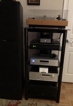
On a bright side, look at the photo; since light is already inside, all it takes to implement a power on indicator is to drill a nice hole and add from the inside a little nice acrylic window. Done!
Attachments
But it can be argued that nobody listens a vinyl at >200W/channel.
Not exactly sure, what you mean ???
Here vinyl is often played with 600w peak into my Maggies 3.6R´s. It´s not too loud, and the Maggie´s love the power 🙂
The common mode issue with floating PS is the same you have with isolated ECG amplifiers (I worked for more than 20 years at HP / Agilent in the medical devision, here ECG headamps need to be floating due to safety requirements) where the patient is 'coupled' to the surrounding 50/60 Hz hum field by it's own body capacitance to earth. Reducing the common mode signal was usually done by keeping coupling capacitance to the grounded part as small as possible and to actively null the common mode input signal by driving one ECG cable ('Right Leg Drive') with an 180 phase copy of the input common mode signal.
As this active nulling strategy is not really feasable for a MC head amp (in contrast to the ECG amp, bandwith is extremely wide) keeping this effect low for MC headamps is to use floating battery supplies in a well shielded case together with the amp in very close proximity and make all the stray capacitances from the two floating power supply rails to the main system ground and to the noise/hum source as small as possible. Changing the hum level by exchanging an amp in the chain following the headamp is simply due to the fact that different amplifiers have different leakage impedances from their own ground to mains earth. Higher impedances (= smaller stray cap) means smaller hum currents in the loop.
Running twoe Duraglit like headamps in balanced mode as Hans is trying may help as well, but only if the common mode signal coupling is identical for both parts of the balanced amp as both chains need their own floating supply.
When using solar cells, keeping the LED drive outside and isolated from the headamp case and coupling light into the solar cells inside via lightpipes would be the logical consequence for using such a power concept. If this approach seems to be too complicated, I would use the grounded dual rail supply approach a la Newton type of headamp as those do not have the basic issue of common mode coupling into the supply rails - every coupling creates differential signals which can be well filtered by standard DC regulators and filters.
Last edited:
There's something funny in the difference between using the wall-wart & the Mean Well in #375.
syn08's circuit doesn't show important stuff like the chassis and where the chassis connections are made.
But if the noise is coming in on J102 (connected to the wall-wart or Mean Well) it can only get to J101 via 3 routes.
The earthing system has to be more like the powered Duraglit I show in my original document but with extra ceramic decoupling caps on the lines at entry points to chassis. The chassis is separate from signal earth and only used for shielding. 2 core + shield all the way helps. You may also need external clip on inductors on known noisy lines entering the box.
For Bonsai, using an existing supply in the integrated amp / preamp, that doesn't cause problems with other parts of the circuit, for the LEDs, is another probable cure .. as the earthing system will have been thought out.
syn08's circuit doesn't show important stuff like the chassis and where the chassis connections are made.
But if the noise is coming in on J102 (connected to the wall-wart or Mean Well) it can only get to J101 via 3 routes.
- Across the LED/Solar Cell via poorly laid out PCB with a lot of capacitance across this Galvanic Isolator. I don't believe syn08 would make such a newbie mistake.
- the 'earth' side of the phonos or the chassis. Classic hum loop / XLR pin 1 problem bla bla. This is one of the things my #1221 procedure checks. Battery Duraglit is much simpler to deal with this. My original document says "The WW battery circuit shows the input connected to the 'chassis' cos the input & output sockets were adjacent to each other. Hence the 'chassis' is really a continuation of the cable shielding braid with all the guts inside the cable"
- RF rectification of stuff coming in via the cables & earth lines. (RF rectification of stuff on the mains of SMPS often appears like mains hum/buzz. You get it even with charging currents on conventional PSUs) For battery Duraglit, I say "The 220p capacitors are NPO / COG ceramics as close to the transistors and the input socket as possible. The 3n3 on the output should probably also be at the output socket too." My #1221 procedure also checks for this.
The earthing system has to be more like the powered Duraglit I show in my original document but with extra ceramic decoupling caps on the lines at entry points to chassis. The chassis is separate from signal earth and only used for shielding. 2 core + shield all the way helps. You may also need external clip on inductors on known noisy lines entering the box.
For Bonsai, using an existing supply in the integrated amp / preamp, that doesn't cause problems with other parts of the circuit, for the LEDs, is another probable cure .. as the earthing system will have been thought out.
@Syn08
I agree with most of what Richard mentions.
It's hard to believe that a few asymmetric pF could couple the 60Hz to the amp.
If so the HF content of the SMPS supply should have an easy life also walking into the signal.
The 60Hz modulated HF content comes into the box where it starts radiating in all directions to be picked up by the input and rectified to 60Hz.
1) While it's quite easy to enlarge the 100pF input caps, this should be a first step to see whether 220pF or higher are making any difference, pointing in the direction of radiation
2) Next step could be to place a 100nF on the entry point of the supply line in the box and put ferrite chokes in the supply line close to the box, to see if reducing HF makes any difference in the 60Hz hum.
3) Then you have used a Mica isolator for the LM7815. I don't know what capacity this present, but it surely acts as a cap and connects the polluted supply line to the box, and thereby to the signal.
By letting this device hang in the air , you could see wether this makes any difference.
Hans
Richard, Hans,
I mostly disagree with your theories; but since for now I’m happy with the results in my system, I’ll let others (why not yourself?) to confirm these theories and experiment various possible general improvement solutions. Welcome to the real, non simulated, world!
One final note, the problem is not related to the box or wiring, since exactly the same issue happens on the desk, without case, regulator mica, etc... when replacing the Agilent 6627A low noise supply with a wall wart.
For the time being, I cleared the desk of this project. There’s other bigger fish to fry.
Last edited:
I have a feeling that the "SuperRegulator" gang would tell you their 2" by 2" PCB will easily outperform the Agilent 6627A in this application. Same for the Linear Audio "Silent Switcher" fans. The SS is a battery powered SMPS followed by an RF-qualified linear regulator (TPS7A4700RGWT -- here is the datasheet).
5V "power bank" battery
5V "power bank" battery
I have a feeling that the "SuperRegulator" gang would tell you their 2" by 2" PCB will easily outperform the Agilent 6627A in this application. Same for the Linear Audio "Silent Switcher" fans. The SS is a battery powered SMPS followed by an RF-qualified linear regulator (TPS7A4700RGWT -- here is the datasheet).
5V "power bank" battery
For the purpose of feeding the LEDs (which is what it is used here for) the intrinsic quality of the regulator is totally irrelevant. It was said multiple times, the hum is not entering through the light, but through parasitic capacitances.
This low frequency noise has nothing to do with radiated RF noise. All this RF noise produced by SMPS are mostly differential and well filtered. It is simply a matter of a capacitive voltage divider from the mains live line, feeding the SMPS, to the ground of the HiFi system. All the filter caps mentioned are only good for RF noise coming via the amp input conection. They are completely useless for the low frequency common mode noise coupling.@Syn08
I agree with most of what Richard mentions.
It's hard to believe that a few asymmetric pF could couple the 60Hz to the amp.
If so the HF content of the SMPS supply should have an easy life also walking into the signal.
The 60Hz modulated HF content comes into the box where it starts radiating in all directions to be picked up by the input and rectified to 60Hz.
1) While it's quite easy to enlarge the 100pF input caps, this should be a first step to see whether 220pF or higher are making any difference, pointing in the direction of radiation
2) Next step could be to place a 100nF on the entry point of the supply line in the box and put ferrite chokes in the supply line close to the box, to see if reducing HF makes any difference in the 60Hz hum.
3) Then you have used a Mica isolator for the LM7815. I don't know what capacity this present, but it surely acts as a cap and connects the polluted supply line to the box, and thereby to the signal.
By letting this device hang in the air , you could see wether this makes any difference.
Hans
From the live input line, we have at first some capacitance to the ground rail of the DC output. From there we have some capacitance from this ground line, which is going straight into the headamp housing, to the inards of the amp, and here especially to the + and - floating supply rails. From there on we have another quite low impedance coupling to the ground of the HiFi system. And from here it goes straight via wanted or unwanted pathways into the mains earth line.
The important part here is the voltage drop across the capacitance between the LED driving lines and the floating power supply lines which is the signal you finally hear. The only measure that may help are the 100nF caps from both LED lines the the housing as these are able to reduce the critical voltage.
I'm a supporter of differential solutions, where many of similar problems are evaded but sorry for you, I have no plans to build your amp.Richard, Hans,
I mostly disagree with your theories; but since for now I’m happy with the results in my system, I’ll let others (why not yourself?) to confirm these theories and experiment various possible general improvement solutions. Welcome to the real, non simulated, world!
In my Inv/Non-Inv Head Amp that will come to live shortly, I will of course report what differences a dirty SMPS versus battery versus Phantom power will make.
A Duraglit is a very nice but sensitive low noise design, should preferably be powered by batteries and is dependant on Hfe.
In your version, Hfe dependancy is eliminated, but open loop gain is very low, making this version unsuited for a wide range of Carts.
With my just slightly more complicated adapted JC design, open loop is expected to be 70dB, with no Hfe dependency, 350pV/rtHz noise and will hopefully be less sensitive to the type of used power supply.
So at least the Mica insulator can be taken from the list, but the same radiation without the box will still be there.One final note, the problem is not related to the box or wiring, since exactly the same issue happens on the desk, without case, regulator mica, etc... when replacing the Agilent 6627A low noise supply with a wall wart.
It's either capacitive coupling, radiation or a combination of both.
Maybe Boydk can give us the final prove and the confirmation whether a differential setup will reduce this sensitivity by temporarily connecting two stereo channels into one mono diff channel.
This would all be very valuable info.
I greatly respect your creative efforts so far and understand that you want to move on with different projects.
Hans
Maybe Boydk can give us the final prove and the confirmation whether a differential setup will reduce this sensitivity by temporarily connecting two stereo channels into one mono diff channel.
Hans
Be happy to, but you´re in for a wait. Right now work takes about most of my spare/free time, so the private projects pile just keeps getting bigger and bigger 🙂
Andreas,This low frequency noise has nothing to do with radiated RF noise. All this RF noise produced by SMPS are mostly differential and well filtered. It is simply a matter of a capacitive voltage divider from the mains live line, feeding the SMPS, to the ground of the HiFi system. All the filter caps mentioned are only good for RF noise coming via the amp input conection. They are completely useless for the low frequency common mode noise coupling.
From the live input line, we have at first some capacitance to the ground rail of the DC output. From there we have some capacitance from this ground line, which is going straight into the headamp housing, to the inards of the amp, and here especially to the + and - floating supply rails. From there on we have another quite low impedance coupling to the ground of the HiFi system. And from here it goes straight via wanted or unwanted pathways into the mains earth line.
The important part here is the voltage drop across the capacitance between the LED driving lines and the floating power supply lines which is the signal you finally hear. The only measure that may help are the 100nF caps from both LED lines the the housing as these are able to reduce the critical voltage.
While writing my posting, I missed your in between posting.
Since you have build up quite some knowledge in this particular field, I accept what you are telling.
Since I'm very visually oriented, I would have loved to see a schematic diagram, since this not only shows the problem, but can also be used to find possible solutions such as a differential topology or whatever.
But thanks anyway for taking the time to explain several times.
Hans
- Home
- Source & Line
- Analogue Source
- Richard Lee's Ultra low Noise MC Head Amp