I fully agree with Scott that all this electrical damping, as good as it sounds, is blabla.Based on what few measurements I have seen too high a load R is the thing to avoid. Even though a square wave response doesn't show additional ringing the sound gets, for want of a better term 'splashy'.
Is there any substantial theory that could explain what you call 'splashy' sound for such high load R cases or is it pure psychology? (You know those guys explaining that too low R is damping too much must also claim that a too high R underdamps - logic does not allow anything else 🙂🙂🙂)
These gain figures are at LF, not 1000 Hz I assume?
No, they are @1000Hz. A little high, but that’s why I have a line preamp in between. Extra gain never hurts.
.
Is there any substantial theory that could explain what you call 'splashy' sound for such high load R cases or is it pure psychology?)
as R increases you will get a resonant peak appearing somewhere above the audio band. This much is simple RLC analysis. Why it was heard when there was no obvious additional ringing on the square wave I cannot say and I have not tested personally, but the report came from a grumpy pro-audio type who dislikes audiophiles🙂
I prefer high input impedances for MC cartridges because they sound more 'airy' than when they are fed into a virtual ground. I mean, think about it. If you tie a rock around a birds neck it can't fly and it can't really sing (the rope will be pushing on its voice box). This is the same as feeding an MC cart into a virtual ground. Take the rock off the bird's neck (i.e. feed the cart into a high Z input) and it can sing and fly - the MC cartridge as well.
I know I am right because this makes perfect sense to me . . .
I know I am right because this makes perfect sense to me . . .
________________
Soft Magnetic Materials for Audio Transformers: History, Production, and Applications
This is a fascinating article with much of practical use today. IIRC, Old Man Sowter talks about 'glass metal' cores which might the special 'ferrites' that Marik uses in his transformers & ribbons.
________________
Also available here for non AES members (entitled 'GAVSowter')
That's why I'm building a Hi Z and a Virt Gnd head amp based on the same amplifier module. If not it would be comparing apples to pears.I prefer high input impedances for MC cartridges because they sound more 'airy' than when they are fed into a virtual ground. I mean, think about it. If you tie a rock around a birds neck it can't fly and it can't really sing (the rope will be pushing on its voice box). This is the same as feeding an MC cart into a virtual ground. Take the rock off the bird's neck (i.e. feed the cart into a high Z input) and it can sing and fly - the MC cartridge as well.
I know I am right because this makes perfect sense to me . . .
Because they are Diff-In and switchable to SE, all 4 possible variants can be compared between topologies.
It will satisfy my need to know if any differences can be heard.
My design is now ready to be implemented , almost back to the original design with the LT1884 and should be insensitive to Vbe differences and have low switch-on / switch-off currents.
Hans
Thank you.Also available here for non AES members (entitled 'GAVSowter')
I have great respect for people going in miniscule detail in 1944 without the help of any computer or even a calculator or a wordprocessor.
To make such a 235 pages paper much have taken months to produce.
Hans
I tend to fully agree. The only thing that can be said for sure is that, if you go significantly lower than 100R with a voltage input amp (and 99% of commercial MC amps are voltage input), signal level will get attenuated and thus reduces output level and worsens SN. For cartridges with Rs > 30R the 100R already have an audible effect while for an Rs of 3R, one can go lower before this attenuation gets significant. As the majority of cartridges today are in the 5 to 15R range, the 100R recommendation or the rule of thumb to use 10*Rs fits the bill for most cases.
And if output level is not adjusted when listening and comparing different input resistor values, the louder setting will in most cases be preferred. And the majority of people do not realize that when playing with the DIP switches on their MC preamp, they change output level.
For this particular topology in #375 is not that bad; I discussed this before in this thread in multiple posts, let me summarize.
#375 can be viewed as a feedback amplifier in inverting configuration (or as an amplifier with emitter degeneration); the closed loop gain is given by:
Acl=A/[1+A*(Rs/Rl)], where Rl=R100||R107=R100/2 and Rs is the cartridge resistance.
A (the open loop gain) is remarkably independent of the bias current and has the expression
A=(Vcc-2Vbe)/Vt where Vt=kT/q=26mV @25 degrees. This is because Rl sets both the transconductance and is the load, so the product is actually constant.
This explains why I choosed to put an extra regulator - we don't want to have the current source locally heat the board and change (decrease) the open loop gain. Now, if the open loop gain would be large enough, then we could approximate the closed loop gain as Acl=Rl/Rs however for feeding #375 from a low voltage solar cell (Vcc=2.7V) this is not possible; the open loop gain is only some 28dB at room temperature.
The closed loop gain Acl depends on the cartridge impedance and it increases when Rs decreases. If we plot a chart of Acl vs. Rs, the closed loop gain will start from A at Rs=0 and it decreases asymptotically to zero. It is remarkable that, from a cartridge perspective, the S/N is rather constant for all cartridge resistances; both the gain for the cartridge signal and the Rs noise is exactly the same.
Now, from the amplifier perspective, there is an optimum for the bias current, that also depends on the cartridge resistance Rs. This was discussed phenomenologically in #555. Essentially, if the bias current Ic is increased (to lower the noise, since the RTI goes down with SQRT(1/2gm)), the gain also decreases (since the input impedance goes with 1/2gm so there is a deeper voltage divider). So the resulting S/N decreases ~1/SQRT(2gm) or ~1/SQRT(2Ic). OTOH, at very low collector current increasing the collector current (in the uA range) actually increases the S/N since the collector current noise SQRT(2qIc) has a smaller overall contribution. This bias optimum (for the S/N) was derived algebraically in #577, Hans also got it in simulation in #629. It is not a deep optimum, it is rather flat, but at these levels every drop may count. For my 12ohm MC Benz Micro Gold cartridge this optimum is at about 2.5mA, hence the bias choosen for the practical implementation.
This pretty much covers it. Regarding a balanced version, I have to consider the pros and cons. I have no idea right now how sensitive the CMRR would be to the natural tolerances, in particular for the open loop gain that depends on the solar cell illumination (through Vcc). It could be a good idea but needs more analysis.
Last edited:
@richard. I am pretty sure that 'glass metal' is what we call in the 21st century 'amorphous core' and is std or an option on most MC trafos now.
I prefer high input impedances for MC cartridges because they sound more 'airy' than when they are fed into a virtual ground. I mean, think about it. If you tie a rock around a birds neck it can't fly and it can't really sing (the rope will be pushing on its voice box). This is the same as feeding an MC cart into a virtual ground. Take the rock off the bird's neck (i.e. feed the cart into a high Z input) and it can sing and fly - the MC cartridge as well.
I know I am right because this makes perfect sense to me . . .
I would expect this sort of argument and conclusion from mmerrill99, not from you...
aw cmon lets have a stupid* Faraday vs Lorenz discussion 😀
*seriously I have seen one of those on a cartridge thread.
*seriously I have seen one of those on a cartridge thread.
Such an RLC resonance is also not really useful to explain such behaviour. With an input capacitance incl. phono cable of 1nF (which is already very high) and an MC cart with 100 µH inductance (which is also at the upper corner for available MC carts), the resonance will be around 500 kHz. You need to increase the capacitance to > 100 nF to bring the resonance to 50 kHz or lower.as R increases you will get a resonant peak appearing somewhere above the audio band. This much is simple RLC analysis. Why it was heard when there was no obvious additional ringing on the square wave I cannot say and I have not tested personally, but the report came from a grumpy pro-audio type who dislikes audiophiles🙂
aw cmon lets have a stupid* Faraday vs Lorenz discussion 😀
*seriously I have seen one of those on a cartridge thread.
One can sit on his toes and shout blue in the face "murder", cartridges are still not reciprocal motors.
BTW, resonances in the audio band for MM cartridges can indeed be a problem, but because of a too high capacitive loading. Making the real part of the input impedance lowish to amortize these resonances (if this is what you mean) is IMO only working around the issue in a badly designed MM preamp.
I would expect this sort of argument and conclusion from mmerrill99, not from you...
😀 it’s FRIDAY
as R increases you will get a resonant peak appearing somewhere above the audio band. This much is simple RLC analysis.
This is all electrical, the motor is not involved. The high frequency resonances of the cantilever are flectural and torsional and there are transmission line elements making it a non-minimum phase system. This is a non-trivial problem.
MMs are their own problem as the hundred of pages on here on this shows 🙂. Making a good MM preamp is my major fetish at the moment.BTW, resonances in the audio band for MM cartridges can indeed be a problem, but because of a too high capacitive loading. Making the real part of the input impedance lowish to amortize these resonances (if this is what you mean) is IMO only working around the issue in a badly designed MM preamp.
Whole system is indeed non-trivial and suprising it works at all🙂 But if damping doesn't happen and people aren't imagining things (possible) then there is something in the simple tuned circuit going on.This is all electrical, the motor is not involved. The high frequency resonances of the cantilever are flectural and torsional and there are transmission line elements making it a non-minimum phase system. This is a non-trivial problem.
Personally I never change the resistive loading on MCs so it really should be a big 'meh' from me !
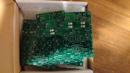
Heyyy SYN08..... Result of your gracious sharing of gerbers 🙂
One question though, where do you source those 3900uF polymer cap´s??
I´m having a really hard time finding anything larger than 1500uF (if that big) over here.
Nice PCB’s. Where did you have them produced.
I always used Beta LAYOUT, but they are becoming almost prohibitive expensive.
Hans
Heyyy SYN08..... Result of your gracious sharing of gerbers 🙂
One question though, where do you source those 3900uF polymer cap´s??
I´m having a really hard time finding anything larger than 1500uF (if that big) over here.
< PLG0E392MDO1 Nichicon | Kondensatoren | DigiKey >
Air transport is free for parts value > €50. Less than 2 days usually to my doorstep.
They use UPS.
syn08, this is an excellent and accurate description of a my wonky virtual earth. 🙂 Guru Hans shows Duraglit is equivalent to this ... as is #375#375 can be viewed as a feedback amplifier in inverting configuration (or as an amplifier with emitter degeneration); the closed loop gain is given by:
Acl=A/[1+A*(Rs/Rl)], where Rl=R100||R107=R100/2 and Rs is the cartridge resistance.
A (the open loop gain) is remarkably independent of the bias current and has the expression
A=(Vcc-2Vbe)/Vt where Vt=kT/q=26mV @25 degrees. This is because Rl sets both the transconductance and is the load, so the product is actually constant.
This explains why I choosed to put an extra regulator - we don't want to have the current source locally heat the board and change (decrease) the open loop gain. Now, if the open loop gain would be large enough, then we could approximate the closed loop gain as Acl=Rl/Rs however for feeding #375 from a low voltage solar cell (Vcc=2.7V) this is not possible; the open loop gain is only some 28dB at room temperature.
The closed loop gain Acl depends on the cartridge impedance and it increases when Rs decreases. If we plot a chart of Acl vs. Rs, the closed loop gain will start from A at Rs=0 and it decreases asymptotically to zero. It is remarkable that, from a cartridge perspective, the S/N is rather constant for all cartridge resistances; both the gain for the cartridge signal and the Rs noise is exactly the same.
Now, from the amplifier perspective, there is an optimum for the bias current, that also depends on the cartridge resistance Rs. This was discussed phenomenologically in #555. Essentially, if the bias current Ic is increased (to lower the noise, since the RTI goes down with SQRT(1/2gm)), the gain also decreases (since the input impedance goes with 1/2gm so there is a deeper voltage divider). So the resulting S/N decreases ~1/SQRT(2gm) or ~1/SQRT(2Ic). OTOH, at very low collector current increasing the collector current (in the uA range) actually increases the S/N since the collector current noise SQRT(2qIc) has a smaller overall contribution. This bias optimum (for the S/N) was derived algebraically in #577, Hans also got it in simulation in #629. It is not a deep optimum, it is rather flat, but at these levels every drop may count. For my 12ohm MC Benz Micro Gold cartridge this optimum is at about 2.5mA, hence the bias choosen for the practical implementation.
Da beach bum could never conjure up the poly-syllabicity for such an erudite statement. 😱 Please may I use your explanation when I am pre10ing to unnerstan such issues?
__________________
Incidentally, please note that syn08's #375 is now the lowest noise, practical, real life MC head amp in da known universe, usurping the various Duraglit versions that have held the title for nearly 40 yrs.
I eagerly wait for someone to construct & use a solar cell powered Duraglit running zillion mA to wrest the title back ... but in the meantime ...
It appears the use of #375 has beneficial effects on World Peace like Duraglit. I'm too prudish to ask for DBTs on syn08's sex life 😀
- Home
- Source & Line
- Analogue Source
- Richard Lee's Ultra low Noise MC Head Amp