Yes in my loopback test there is more harmonics. I do not know why. I used simple settings: no effects, volume to the level that produces same amplitude as the original RMAA test file is. Then RMAA compared the original test file and file I've recorded.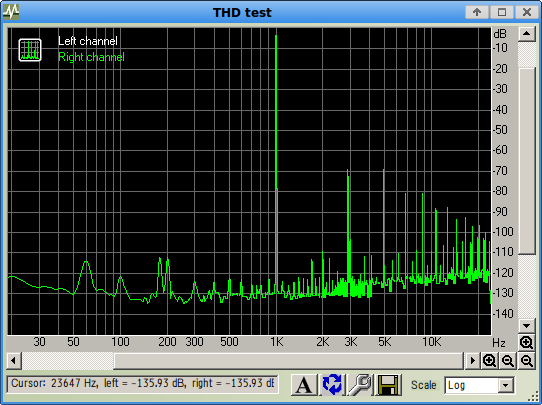
Everything may impact sound - computer PSU, Wi-Fi router ...
Also, despite they named 0404, cards are totally different. Mine is PCI, the card from yours link is USB.
Hi Ian,
I read here
Articles/Updates
BTW did you test 6C45P-E for noise? Is it still worse than 6922?
The bottom line is that, of all the tubes I have tested, the ECC88/6922 is consistently lower noise than any other tube I have tested. In theory, using two in parallel should reduce the noise they produce by 3dB.
I read here
Articles/Updates
Is it correct that cascode can reduce noise?The 6C45pi Tube:
This is a heavy duty Russian military tube that is unlike any other. At the plate current levels used, it has more than twice the transconductance of the commonly used 6922 tube. Also, gain is 65% higher. These two factors combine to yield a much lower noise figure than is possible with any other current production vacuum tube. The first stage employs cascoding for lowest possible noise.
BTW did you test 6C45P-E for noise? Is it still worse than 6922?
Cascode has less noise than an equivalent pentode circuit, but no better than a triode for valve noise. PSRR is poor so you need to do something about supply rail noise.mm7 said:Is it correct that cascode can reduce noise?
Use a cascode when you need low input capacitance or high voltage gain, but can't afford the noise of a pentode and are willing to cope with the poor PSRR.
Cascode has less noise than an equivalent pentode circuit, but no better than a triode for valve noise. PSRR is poor so you need to do something about supply rail noise.
Use a cascode when you need low input capacitance or high voltage gain, but can't afford the noise of a pentode and are willing to cope with the poor PSRR.
So, if from the noise perspective CC triode is better, will be one 6C45P-e better than two parallel 6922?
What would you say about following schema. Here are two Mu follower stages on 6C45P-E that give approximately same amount of gain ~87dB with input tranny.
Will this power fressing beast be more quiet than the previous one based on 12AX7 6N23P?
Would it make sense to reduce current through 1-st stage?
Will this power fressing beast be more quiet than the previous one based on 12AX7 6N23P?
Would it make sense to reduce current through 1-st stage?
Attachments
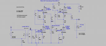
What would you say about following schema. Here are two Mu follower stages on 6C45P-E that give approximately same amount of gain ~87dB with input tranny.
Will this power fressing beast be more quiet than the previous one based on 12AX7 6N23P?
Would it make sense to reduce current through 1-st stage?
It is difficult to say if it will be quieter and if so by how much. As I said before, you probably have no more than a 6dB improvement available before you hit the laws of physics. If you believe the high mu equals less noise myth then it may well improve the noise. Certainly the 12AX7 is not the quietest tube nor is the 6922 but we are only talking a few dBs to be gained.
As I may have mentioned before, I have achieved a measured -125.5dBu EIN with a 6CG7 and my measurements indicate the 6922 is slightly quieter. There are quite a few single hi mu triodes including the relatively cheap Russian 6C3N which has a mu of 50 and a gm of 20. I recently purchased a few of these with the intention of trying them in place of a 12AX7 in one of my current preamp designs to see it there was any noise improvement but I had not yet had chance to do that.
The only way to know for sure is to get a couple of tubes and try it yourself. There is no point in doing it other than in the first stage.
Cheers
Ian
I do not believe the high mu equals less noise myth, rather I believe high gm may give less noise myth. 🙂It is difficult to say if it will be quieter and if so by how much. As I said before, you probably have no more than a 6dB improvement available before you hit the laws of physics. If you believe the high mu equals less noise myth then it may well improve the noise. Certainly the 12AX7 is not the quietest tube nor is the 6922 but we are only talking a few dBs to be gained.
Intuitively I feel, if to run a powerful tube with a fraction of its full power capability, it should produce less hiss than a less powerful tube run with same power, on edge of its full capability. I may be wrong. But I am seeing a number of low noise designs based on powerful tubes (high gm).
Like these:
:: View topic - Real World All Tube LCR Phono for MC Without SUT
Transcendent Sound Phono Preamp
-125.5dBu EIN is impressive. Could you provide with details?As I may have mentioned before, I have achieved a measured -125.5dBu EIN with a 6CG7 and my measurements indicate the 6922 is slightly quieter.
There are quite a few single hi mu triodes including the relatively cheap Russian 6C3N which has a mu of 50 and a gm of 20. I recently purchased a few of these with the intention of trying them in place of a 12AX7 in one of my current preamp designs to see it there was any noise improvement but I had not yet had chance to do that.
6C45P is also single hi mu (70), hi gm triode.
From datasheets:
6C45P has Equivalent noise resistance, KOhm 0.1
6C3P has <0.2k ( ''GSTube.com''. Tubes, sockets etc. Parameters and characteristics 6C3n-EB )
I understand that datasheets may be too optimistic. But still 6C45P looks has less noise.
Did you have any chance to try it?
Yes, of course. But it also make sense to ask experienced and knowledgeable people. 🙂The only way to know for sure is to get a couple of tubes and try it yourself. There is no point in doing it other than in the first stage.
fwiw I have someone's old diy tube mixer - outboard unregulated supply, decent transformers, left-center-right switches, 12ax7 cascode - very quiet with my Beyers. dunno how transparent but better than my pcm 501 at the time.
http://img218.imageshack.us/img218/5199/mixcg4.jpg
http://img218.imageshack.us/img218/5199/mixcg4.jpg
fwiw I have someone's old diy tube mixer - outboard unregulated supply, decent transformers, left-center-right switches, 12ax7 cascode - very quiet with my Beyers. dunno how transparent but better than my pcm 501 at the time.
http://img218.imageshack.us/img218/5199/mixcg4.jpg
Interesting. What kind of transformers? What left-center-right switches are for? What Beyers are? Are these ribbon mics?
The challenge with a ribbon mic - it produces very weak signal.
The more HF you want from it - the less level of signal it produces. My mic was designed for FR up to ~18-20kHz.
Thus it produces ~28uV for speach level sound 60dDb SPL.
And it is after multiplying by 37 by its Lundahl 2913 transformer.
Practice shows that it can be further increased up to 5 times by additional Lundahl 1935 transformer that is part of preamp. However if the transformer set to 1:10, it dramatically impacts LF and HF. That means - energy that the mic gets from sound cannot be multiplied more than 37*5=185 times. Even when it enters into very Hi Z input tube stage. 28uV * 5 = 140uV. Signal of this level has to be amplified by first tube.
Target is to add as less noise to this signal as possible.
If your mixer can work with such levels (~30uV) quietly it would be very respectful product. Could you please share details, especially what are input transformers there.
PS/ Nice little cans are there. What kind of beer is it?🙂
I do not believe the high mu equals less noise myth, rather I believe high gm may give less noise myth. 🙂
LOL, I meant gm of course.
The first one gives no figures for noise achieved but it uses my favourite mu follower topology so there is no reason it should not be good. The second one quotes a gain of 52dB and a signal to noise of 75dBA which is an EIN of -127dBA. So for a start it is A weighted which always makes the figure better. Second the S/N figure does not specify an output level but hifi guys tend to use 1 volt as a reference so this becomes -125dBu (A weighted)But I am seeing a number of low noise designs based on powerful tubes (high gm).
Like these:
:: View topic - Real World All Tube LCR Phono for MC Without SUT
Transcendent Sound Phono Preamp
-125.5dBu EIN is impressive. Could you provide with details?
It's nothing spectacular, just a couple of 6CG7 mu followers with a gain control in between and a Sowter 1:10 input transformer. The basic schematic of the mu follower stage is shown at the bottom left of this schematic:
http://www.ianbell.ukfsn.org/EzTubeMixer/docs/PMEQP1A/PMTGMUcctjpeg
6C45P is also single hi mu (70), hi gm triode.
From datasheets:
6C45P has Equivalent noise resistance, KOhm 0.1
6C3P has <0.2k ( ''GSTube.com''. Tubes, sockets etc. Parameters and characteristics 6C3n-EB )
I understand that datasheets may be too optimistic. But still 6C45P looks has less noise.
Did you have any chance to try it?
The data sheets only give the noise resistance for radio frequencies. There is no reason to think they will be he same at audio frequencies where flicker noise is an important component.
I will try it when I get moment but right now I have several other projects I need to first complete.
Cheers
Ian
Last weeks I've got a set of 6S45P tubes and passive parts to make new preamp based on these tubes.
This time I've separated PSU and signal units. Regarding to this separation I have question. I prefer to keep electrical things safe and connected both aluminum boxes with Earth wire. So umbilical cable includes: B+, heater+, heater-, Ground and Earth.
The Earth is connected to the Earth prong of power connector, and another end is bolted to aluminum PSU chassis to its rear panel, then from this bolt, via the umbilical cable it runs to Preamp aluminum chassis, where it is bolted too to its rear panel.
Ground wires are connected star-wise with the star center attached to Ground pin of input XLR that is located on front panel of chassis. One ground "beam" wire goes back via umbilical cable into PSU, but Ground of PSU is not connected to its chassis.
I hope this is correct and should not cause buzz and hum. Am I right? Is it OK to have the Ground center on front panel and Earth on rear panel? Will it create a ground loop?
Secondly,
I did not expect that these 6S45P beasts are very sensitive to RF and oscillate like crazy birds. I read that there are 3 ways to prevent oscillation:
1 - use shortest leads and connect parts directly to tube sockets. That is what I've done. Does not help.
2 - use stopper resistors at all signal pins of a tube socket. 6S45P has 4 cathode pins, two grid pins, plate. So it will need to solder 7 resistors per a socket.
3 - use ferrite beads on all signal pins/wires.
Which way 2 or 3 is better? I am afraid that metal film resistors are not effective to stop RF, but composite ones may add some hiss.
I tend to use ferrite beads instead. I am going to place them not only on signal leads at tube sockets but also on B+ and ground and heater wires, as well as on umbilical cord.
Am I right? Any drawbacks of this method?
Any advises what types or ferrite mixes to use? Do exist tube sockets made of ferrite?
Any other advises or suggestions?
Thanks!
I think you have the found right. Protective safety ground bolts to the chassis near were the power comes in and signal ground near the input jack.
If oscillation is a problem, stopper resisters on the grids will help. But also look at the physical layout. You need to have the filter caps for B+ near the loads. Most of them are likely in your power supply box but make sure each load (tube) has a filter cap close by.
Also are you suing shielded leads for hookup wire? I use wielded wire for any signal that feeds a high impedance The idea is to prevent positive feedback via either signal or power supply
Many amps use crcrc filters with taps for different B+ voltages. This is a good design to prevent positive FB via power.
Finally importantly how is the NFB loop designed? There needs to be some higher frequency "compensation". You can squash the gain above some frequency.
You can't have osculation without positive feedback.
ChrisA,
yes 3 CR filter stages are in PSU box.
two CRs (100uF motor run cap and 500R) are in Preamp box. They are in parallel for stage decoupling. One of this CRs is for 1-st preamp stage, another for second stage. Also bypassed with 0.1uF caps.
I use shielded leads only for first grid wire. where signal is very tiny.
there is no NFB (except cathode Rs). Shematic was published here, it mostly same except the tubes.
What about ferrite beads?
here the layout is. blue/green wires is heater, red is H+ (except attenuator), black is ground. Blue is signal.
Attachments
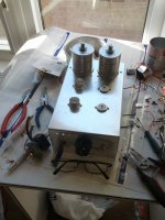
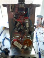
May be it is overkill, but I've done following for each tube:
- put cathode 10R stoppers on all 4 cathode pins, connected other sides, put ferrite bead on this connected "cathode";
- put ferrite bead on each of 2 grid pins, and connected them together as "grid";
- put ferrite bead on anode pin, and each heater pin;
Also I've put ferrite bead on umbilical, though there was no oscillation after I've done the above.
Now there is only some hiss, no oscillation, no audible buzz, no hum.
Though tube 1 produces some microphonics, if knocked.
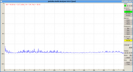
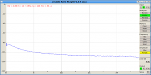
I've took noise measurements. Inserted 150R MF resistor into input XLR and measured output at different volumes.
It shows noise is less by 5 - 10dB, but is not that linear as it was with previous preamp based on 12AX7.
Here are the pictures, first is previous preamp based on 12AX7 and 6N23P. Second is this preamp based on 6S45P-E.
Is this pinkish non-linearity of noise caused by ferrite beads?
It shows noise is less by 5 - 10dB, but is not that linear as it was with previous preamp based on 12AX7.
Here are the pictures, first is previous preamp based on 12AX7 and 6N23P. Second is this preamp based on 6S45P-E.
Is this pinkish non-linearity of noise caused by ferrite beads?
Attachments
I read that the flicker (and shot) noise is a function of current. (here Tube Noise - Professional Vacuum Tube Audio ).
What is a risk in reducing Ia too low? Let say if it is documented that 6S45P-E min Ia is 28mA, what will happen if I set it to be 10mA, or 1mA or even less. Grid signal amplitude is very tiny in my case - +-150uV, so not much distortion is expected. I tried to reduce Ia down to 135uA in LTSpice, the simulation works perfectly well. What should happen in reality?
What is a risk in reducing Ia too low? Let say if it is documented that 6S45P-E min Ia is 28mA, what will happen if I set it to be 10mA, or 1mA or even less. Grid signal amplitude is very tiny in my case - +-150uV, so not much distortion is expected. I tried to reduce Ia down to 135uA in LTSpice, the simulation works perfectly well. What should happen in reality?
LOL, that web page is mine!. I had forgotten I had done that. You will have gathered from that article that as you reduce plate current, shot noise gets higher and flicker noise gets lower. In the tubes I tested , they were about equal at around 1mA. If you reduce it any further, shot noise starts to become bigger than flicker noise and the total noise increases. So there is an optimum plate current for minimum noise for a given tube.
In general there is no such thing as a minimum current for a tube and I see no reason not to run the 6S45 at 1mA. Best thing to do is build it and measure the noise at different currents. Try 1mA, 5mA and 10mA for starters.
Cheers
Ian
In general there is no such thing as a minimum current for a tube and I see no reason not to run the 6S45 at 1mA. Best thing to do is build it and measure the noise at different currents. Try 1mA, 5mA and 10mA for starters.
Cheers
Ian
- Status
- Not open for further replies.
- Home
- Amplifiers
- Tubes / Valves
- Ribbon Microphone Preamp