TDA2003 power IC has 70k input impedance and it was always perplexing for me how come that app note shows circuit without input resistor.......
R6 is the input bias resistor. The input is NOT at ground but up at 1.2V. They generate the 1.2V reference internally so the car-radio designer doesn't have to.
And this is quite off-topic in an RIAA thread.
Attachments
Yes, the headroom is required above all for clicks and pops. When headroom is high small damages of the record and dirt in the groove is less intrusive.
R6 is the input bias resistor. The input is NOT at ground but up at 1.2V. They generate the 1.2V reference internally so the car-radio designer doesn't have to.
And this is quite off-topic in an RIAA thread.
I admit that it is off topic. But it somehow looked to me that it is connected with input impedance synthesis which was mentioned concerning RIAA stage 47k input.
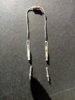
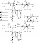
This is the latest PCB layout named "RIAA dual opamp Hifisonix" because it uses Bonsai's parts values which are very convenient and easy to find. PCB is much smaller than Bonsai's, so small that it can fit into turntable together with another small regulated PSU board, and save you the cost of enclosure. Transformer should be as far as possible from the turntable or phono stage enclosure connected with long cable. PCB uses dual opamp, unlike Bonsai's PCB that uses two single opamps. There are three options that can be used for bypass:
1. RC filtering (marked 10R and 100u on the board, but 100u can be anything higher than that, any polarizing elco with 2,5mm lead spacing and 7mm diameter that can fit)
2. Bypass using 100u and 100n with jumper wires instead of 10R resistors
3. Everything soldered just as marked on the board
Gain setting resistor (75R) and cartridge loading capacitor (100p) can be changed easily by fitting soldering pins instead of components and components soldered to corresponding sockets. That way you don't have to desolder anything on the PCB. (PCB is double sided and desoldering is difficult. All tracks are on the top layer and ground plane is on the bottom layer) See pic. I removed component names from the silk screen but it's not difficult to recognise footprints for different component values (like those from davidsrsb/DNi sims or original LM833 app note) DC blocking cap is not bipolar but two back-to-back connected polarizing elcos (1000uF/16V).
Most vinyl users won't need anything better than this.
Attachments

Series output cap is polarizing 22u elco. Before soldering this cap and it's coresponding 100n parallel cap one should first measure DC offset. If it's positive than you should solder 22u cap just as footprint shows. If DC offset is negative 22u cap should be connected in reverse.
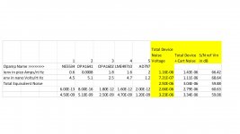
As discussed a few days ago, here are the results of an opamp comparison for RIAA phono EQ amplifier usage. I've used SY's excellent spread sheet to output the generator + 47k loading resistor self noise across 10 bands and then use that data, plus the opamp specified enoise plus inoise to generate an additional total amplifier noise voltage per band. The two noise terms per band are them RMS summed to arrive at the total input referred noise per band and then the ten bands are RMs summed in turn. The result is noise equalized taking into account the action of the RIAA curve which boosts frequencies below c. 500 Hz and attenuates frequencies above 2.1kHz relative to the mid band 1 kHz gain.
As you can see, the NE5534 and the OPA1641 have a c. 8 dB advantage over the other opamps in this application. With the OPA1641, if you use a quad and parallel all the amplifiers as diyaudio member jcx suggested, the equivalent enoise is then half of that of a single amplifier (so 2.5nV/rt Hz) and you get an extra 2-3dB improvement at c. 71 dB.
The important lesson from all of this is that you must use a low input noise voltage opamp, but that has to also have low input noise current. The OPA 1641 is outstanding in this regard and inoise is virtually negligible), but the NE5534 holds up remarkably well for a c. 40 year old design. Further, in any competently design RIAA MM EQ amp, the cartridge and loading resistor noise dominate.
Attachments
Last edited:
Why no OPA1656?As discussed a few days ago, here are the results of an opamp comparison for RIAA phono EQ amplifier usage.
A few suggestions,Series output cap is polarizing 22u elco. Before soldering this cap and it's coresponding 100n parallel cap one should first measure DC offset. If it's positive than you should solder 22u cap just as footprint shows. If DC offset is negative 22u cap should be connected in reverse.
1) why not use a Nichicon UES type BP ecap and not have to worry about this? These are excellent performing parts, here is a selection for you to choose from
Nichicon UES Series Bi-Polar/Non-Polar Electrolytic Capacitors Radial Aluminum Electrolytic Capacitors - Radial Leaded | Mouser Canada
2) Why not use the guaranteed/selected/tested low noise NE5534A?
3) use the Quasi-differential Input arrangement
Attachments

Unfortunately OPA1641 is available only in SOIC package. Therefore, for DIY, NE5534 is still unbeatable and easy to find part stocked by almost all electronic parts shops. (Yes, some of us still buy parts in real shops) 🙂
For a small order of parts, like needed for RIAA stage, I think it's unreasonable to order parts from mail order companies. Postage and packing expenses will be too high.
I shall make SMD version of the board for the brave ones who like to use minuscule parts.
For a small order of parts, like needed for RIAA stage, I think it's unreasonable to order parts from mail order companies. Postage and packing expenses will be too high.
I shall make SMD version of the board for the brave ones who like to use minuscule parts.
Last edited:
but the NE5534 holds up remarkably well for a c. 40 year old design.
The NE5534A is the chip to use, not the NE5534. The A version is the low noise selected one. 0.4pA/√Hz, 3.5nV/√Hz
You could look at making it a dual footprint on the pcb, place the SOIC-8 between the DIP-8 as they show in the adapters they sell.Unfortunately OPA1641 is available only in SOIC package.
The NE5534A is the chip to use, not the NE5534. The A version is the low noise selected one. 0.4pA/√Hz, 3.5nV/√Hz
Yes - I only use the A party and just assumed everyone does the same for MM.
"The important lesson from all of this is that you must use a low input noise voltage opamp, but that has to also have low input noise current."
I'm not sure that a low current noise opamp makes much difference. Here is the reason why. These scans are from an old book first published in the 1980s by the MicroSim corporation as a tutorial for Pspice. They had a chapter on noise analysis and one example was a phonograph cartridge, probably a Shure V15IV. The trick for using spice to analyze a phono cartridge noise is in scaling the RIAA equalizer values so the maximum resistor value is only 1 ohm and the RIAA network noise is negligible. The second scan shows the noise at node 3 before equalization and the noise at node 5 after equalization. The RIAA equalization greatly attenuates the high frequency noise. Looking at scan 3 which shows the summed noise, you can see that about half the noise is in the first decade, 20-200 hZ and the other half of the noise in in the 2 decades 200-20,000 hZ. It doesn't look like the high frequency noise (current noise) has much effect.
I'm not sure that a low current noise opamp makes much difference. Here is the reason why. These scans are from an old book first published in the 1980s by the MicroSim corporation as a tutorial for Pspice. They had a chapter on noise analysis and one example was a phonograph cartridge, probably a Shure V15IV. The trick for using spice to analyze a phono cartridge noise is in scaling the RIAA equalizer values so the maximum resistor value is only 1 ohm and the RIAA network noise is negligible. The second scan shows the noise at node 3 before equalization and the noise at node 5 after equalization. The RIAA equalization greatly attenuates the high frequency noise. Looking at scan 3 which shows the summed noise, you can see that about half the noise is in the first decade, 20-200 hZ and the other half of the noise in in the 2 decades 200-20,000 hZ. It doesn't look like the high frequency noise (current noise) has much effect.
Attachments
But the inductance of the cartridge means the reflected noise in it due to current noise rises with frequency, cancelling out your supposed drop off in noise with frequency...
This is why current noise is much more dominant in MM amps - the inductance is typically 0.5H, which is massive, so even 1pA/√Hz gets translated to 30nV/√Hz at 10kHz, which might be about 20dB worse than the amp's actual voltage noise.
The amp's voltage noise _is_ attenuated severely with frequency by the RIAA network of course.
Noise in 20 to 200 Hz range is usually less obvious than in the 1k to 10k range where the hearing is more sensitive. If you A-weight those plots you'd see a different emphasis.
You could look at making it a dual footprint on the pcb, place the SOIC-8 between the DIP-8 as they show in the adapters they sell.
SOIC8 footprint pads in Eagle are too long for that. It would be necessary to make new footprints with shorter pads and making new footprint is not an easy task for DIYer. Prasi could do it but question remains how difficult it would be to hand solder such footprint with shorter pads.
Last edited:

"The important lesson from all of this is that you must use a low input noise voltage opamp, but that has to also have low input noise current."
I'm not sure that a low current noise opamp makes much difference. Here is the reason why. These scans are from an old book first published in the 1980s by the MicroSim corporation as a tutorial for Pspice. They had a chapter on noise analysis and one example was a phonograph cartridge, probably a Shure V15IV. The trick for using spice to analyze a phono cartridge noise is in scaling the RIAA equalizer values so the maximum resistor value is only 1 ohm and the RIAA network noise is negligible. The second scan shows the noise at node 3 before equalization and the noise at node 5 after equalization. The RIAA equalization greatly attenuates the high frequency noise. Looking at scan 3 which shows the summed noise, you can see that about half the noise is in the first decade, 20-200 hZ and the other half of the noise in in the 2 decades 200-20,000 hZ. It doesn't look like the high frequency noise (current noise) has much effect.
in a MM system, about half the total cartridge input referred noise is contained in the top two and half octaves as a result of the rising cartridge inductance. On a typical cartridge ¦Z¦ is as high as 20k Ohms at 20 kHz so amplifier input current noise is an important parameter.
Is there any such opamp that has both very low input voltage and current noise? Usually, if one is very low the other is relatively high.
- Home
- Source & Line
- Analogue Source
- RIAA circuit help needed