Have you looked at OPA1656? it is 4x the price of a ne5534a, its a dual so that could mean it is 2x, not too bad imo.
Attachments
Last edited:
From DIY perspective OPA1656 is not really diy-friendly device because it's produced only in SOIC package.
Also, I doubt that FET opamp, and especially CMOS, will sound OK to me, in this application. My experience is that bipolar opamps are unsurpassed in RIAA applications.
Also, I doubt that FET opamp, and especially CMOS, will sound OK to me, in this application. My experience is that bipolar opamps are unsurpassed in RIAA applications.
IMO it is very easy to solder a SOIC-8, it does not help when people say such scary things to deter folks from at least trying for themselves. Sure it requires a bit of technique, a good iron but that is all part of having good tools and learning.
Do you really think TI/BB would come out with a part like this, with the applications in mind, that sounds bad. It is good to hear you say "Doubt" as that to me means you really are not sure, which is good, because it makes room for opportunity and not a complete shut down of trying it out.
When I have some free time from other design activities, I'll do a small layout using the part and give it a try.
The bigger problem is finding the precision capacitors, esp in through hole, far and few readily available from the usual suppliers. Last night I went looking, if I do up the design it will use MLCC, NPO(COG), much easier to find, in precision tolerances. Even then, one has to parallel devices to get to the values as needed.
Let me guess, you are going to say MLCC(COG) caps sound bad too 🙂 Can they be any worse than a noisy LP 🙂
Last edited:
I think that making troubles for yourself by choosing "superior new" SMD device and trying to find exact part values is not worth the effort when you know that perfectly good RIAA circuit can be made with usual TH opamp and usual E6 values caps (like in Bonsai's circuit). I don't think that SMD MLCC caps sound bad but why use them when very good TH poly caps are available in 5mm lead spacing and values that are easily available. My comment is based on my experiences with j-fet opamps in RIAA circuits. These parts sound warm and fat at first, but soon you find that detail and clarity are missing. Still, if OPA1656 was in DIP package I would try it out of curiosity to see how CMOS part sounds.
I understand that BB must release new "audio quality " products from time to time and that they are motivated to persuade us to buy them but it does not mean that we should swallow the offer line, sinker and hook, especially when it requires extra effort to solder such small part.
I understand that BB must release new "audio quality " products from time to time and that they are motivated to persuade us to buy them but it does not mean that we should swallow the offer line, sinker and hook, especially when it requires extra effort to solder such small part.
How is it trouble, it is play time with this stuff 🙂
I did make one of my first phono pre-amps using a NE5533 back in the late 70's as student. It sounded spectacular at the time. It is a good cheap solution for sure, or they would not still be making NE5534
Yes you are correct, polyester film caps in 5% tolerance are readily available, I was looking for PP types in my search.
What jfet opamps have you tried out for this app?
DIP-ADAPTER-EVM Texas Instruments | Prototyping, Fabrication Products | DigiKey
They make it as easy as they can for us these days.
As you are probably aware, TI does not spend big $ to make parts for DIY, it is for mfgs, if TI thought that there was a need to put the part in a DIP8 they would have. THT is a very expensive and time consuming, compared to auto assembly with smt, tht fine for DIY and power designs, but for mfg, these costs get transferred to the customer in the end.
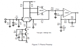
here is another one I was looking at, I did find a mistake 3409 * 2n2 = 7.5us, so it should be 22n for 75us 🙂
I did make one of my first phono pre-amps using a NE5533 back in the late 70's as student. It sounded spectacular at the time. It is a good cheap solution for sure, or they would not still be making NE5534
Yes you are correct, polyester film caps in 5% tolerance are readily available, I was looking for PP types in my search.
What jfet opamps have you tried out for this app?
Do you need for me to solder one onto an adapter for you 🙂 I just bought an adapter pcb from TI, DIP-ADAPTER-EVMStill, if OPA1656 was in DIP package I would try it out of curiosity to see how CMOS part sounds.
DIP-ADAPTER-EVM Texas Instruments | Prototyping, Fabrication Products | DigiKey
They make it as easy as they can for us these days.
As you are probably aware, TI does not spend big $ to make parts for DIY, it is for mfgs, if TI thought that there was a need to put the part in a DIP8 they would have. THT is a very expensive and time consuming, compared to auto assembly with smt, tht fine for DIY and power designs, but for mfg, these costs get transferred to the customer in the end.
here is another one I was looking at, I did find a mistake 3409 * 2n2 = 7.5us, so it should be 22n for 75us 🙂
Attachments
Last edited:
The OPA1656 has very good specs, alas its voltage noise 1/f knee point is very high, ruling it out for low-impedance ultra-low-noise applications, but for a MM cartridge its a good fit. Its nearly rail-to-rail on the outputs allowing low-voltage operation too.
SOIC8 is easy to put on a DIP adapter board - then you can breaboard it or plug into a socket. Try it.
(*) How else are you supposed to interface to 24 bit ADCs and DACs?
SOIC8 is easy to put on a DIP adapter board - then you can breaboard it or plug into a socket. Try it.
They aren't selling it just to you, they have a sound commercial reason for adding it to the product line - quality opamps sell in volume(*) and the competition isn't standing still. Be thankful it isn't VSOP10 package!I understand that BB must release new "audio quality " products from time to time and that they are motivated to persuade us to buy them but it does not mean that we should swallow the offer line, sinker and hook, especially when it requires extra effort to solder such small part.
(*) How else are you supposed to interface to 24 bit ADCs and DACs?
Glad you agree with me Mark 🙂 do you listen to LP's ?
I wonder what Bonsai thinks of the OPA1656?
It is strange that TI only chose the SOIC8 for this device and did not add smaller packages, similar to some of the other parts in the OPA16xx line up. Makes one wonder about the rational behind these decisions.
This is Ivan's thread I should not de-rail it. One option you can do, is to split the gain into two or more sections as Doug Self has done in some of his designs. You could use a jumper block to have gain selection. There is something to be gained as far as lowering the thd with this arrangement, but comes at a cost of power, space, $ of course.
Another addition is a jumper block for C loading options, maybe even R loading options, can be done with a jumper block or a DIP switch arrangement, these can be stuffing options. Kind makes it more universal and allows easier cartridge/cable selection. Just some thoughts for you to consider.
Attachments
Last edited:
I tried TL072 and OPA2134 j-fets. No matter how good specs for j-fets are, they all have the same signature sound, fat and dark, laid-back but not enough clarity. I could solder SOIC8 but it's strain for the eyes and eyes are worth more than any opamp. IT seems that CMOS is new trend with opam manufacturers and I am curious how they sound so I am tempted to try one. OPA1656 seems like a good candidate.
The error that you found in app note is not the only one. There are more of them and recently I found one in app note circuit for Baxandall tone control preamplifier. The value for the cap in HF section was an order of magnitude higher than necessary.
The error that you found in app note is not the only one. There are more of them and recently I found one in app note circuit for Baxandall tone control preamplifier. The value for the cap in HF section was an order of magnitude higher than necessary.
Sy, who left the forum, has a very nice RIAA noise calculator here
SYclotron Audio | RIAA Noise Calculator
This will allow you to compare the real world noise of your RIAA with different opamps with a cartridge connected.
The OPA1656 looks like an excellent opamp, but I could not find a 1/f plot. Ideally you want the 1/f knee to be below 100 Hz for an RIAA amp.
In general, CMOS input opamps have higher 1/f knees than JFET input devices and most bipolar input opamps.
This is probably a subject Scott Wurcer will have a lot of experience in
Last edited:
The way I see it, SY assumes a noiseless active device in his spreadsheet.
BTW, the noise plot of OPA1656 is on the first page of the DS. The 1/f knee is located at approximately 1 kHz.
Regards,
Braca
BTW, the noise plot of OPA1656 is on the first page of the DS. The 1/f knee is located at approximately 1 kHz.
Regards,
Braca
Usually most people feel that digital audio is aggressive in HF and thin sounding. Manufacturers who want to overcome this (subjective) shortcoming of digital audio usually use j-fet opamps in output filter section. I know that NAD used OPA2134 in some of their CD players, and I've also seen TI Excalibur j-fets in some Italian higher class CD players. For the people who feel their CD player needs softer and darker sound, the easiest upgrade is to fit j-fet opamp instead of bipolar in the output filter section. Many people used this trick as less expensive mod than fitting valve.
It's possible that new trend with CMOS opamps for audio is an attempt to make digital formats sound more "analog".
My friend who is owner of the recording studio, can hear great difference between bipolar and j-fet based mixing desks. J-fets are worm and full sounding, while bipolars have much better definition and clarity.
With RIAA circuit, which is by definition analog, better results can be achieved with bipolars. You don't need warmer sound with RIAA, just the opposite, you want more clarity and that's where bipolars excell.
The way I see it, SY assumes a noiseless active device in his spreadsheet.
BTW, the noise plot of OPA1656 is on the first page of the DS. The 1/f knee is located at approximately 1 kHz.
Regards,
Braca
Ahh - I just looked at it very briefly and missed that. Its a pity its that high.
I actually have not looked at Sy's spreadsheet for about 3 years so forgot the detail. I might take a look at this and mod it to include the opamp input noise.
The upshot of all this is that ultimately cartridge impedance and the 47k loading resistor dominate overall noise. Once the pre is 6-10 dB quieter than the cartridge, the returns for lower noise become very small - and of course the vinyl itself is never better than 60 -65 dB S/N
Its possible to synthesize the 47k and substantially reduce its noise. Even though vinyl noise dominates, needle-up noise is white (hiss) and much more noticable at switch-on due to it being the only thing audible before stylus hits groove.
Its possible to synthesize the 47k and substantially reduce its noise.
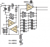
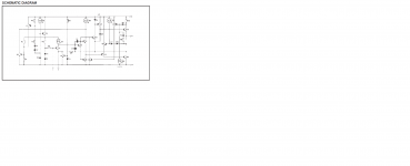
TDA2003 power IC has 70k input impedance and it was always perplexing for me how come that app note shows circuit without input resistor. Could it be that input impedance is synthesized just to save one resistor footprint? I would understand it because it's car radio IC and there is imperative to save PCB place. But for home hifi several components more on the pcb will not be that prohibitive from the cost and pcb size perspective. Does the left side of the schematic represent synthesized input resistor?
Attachments
Its possible to synthesize the 47k and substantially reduce its noise. Even though vinyl noise dominates, needle-up noise is white (hiss) and much more noticable at switch-on due to it being the only thing audible before stylus hits groove.
At normal listening levels you should not be hearing any noise before the needle hits the groove.
You have to draw the line somewhere IMV. With my volume up full and my ear about 100 mm from the speaker all I hear is a gentle shhh. At that level, my system would be pushing out > 200 watts. At normal listening it’s a non issue. Better to focus on the things that matter like hum reduction, accurate conformance, good overload capability etc. Once the needle hits the groove you will never better 60~65 dB.
(BTW my phono gain input to power amp output is 40 x 4 x 28 = c. 74 dB)
Last edited:
At normal listening it’s a non issue. Better to focus on the things that matter like hum reduction, accurate conformance, good overload capability etc. Once the needle hits the groove you will never better 60~65 dB.
Many years ago low noise opamps were available which had supply voltage +/-26,5V, like Hitachi HA12017. Because of it their headroom was unsurpassed.
There is nothing like that available today. I remember that some UK companies used these parts for RIAA circuits.
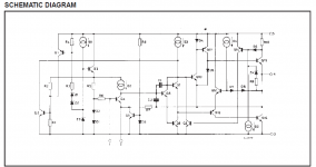
The datasheet is rather cryptic.
Not sure why you really want a lot of headroom for a phono signal, maximum MM output is about 60mV for a nominal 5mV cartridge, typical phono amp gains of 35dB put that at 3V rms or so, higher than most power amp's need. More headroom just means the power amp clips before the phono amp on scratches. Its useful to have a few selectable gain settings so that different cartridge sensitivities can be accomodated in the phono amp.
If you were often switching cartridges and between LPs and 12" singles all the time then I can see the headroom being useful, but changing cartridges isn't something most people do often! Well maybe here...
I think that headroom is beneficial if you want to use Baxandall active/passive RIAA topology which has less headroom at HF. I know that some great RIAA phono stages that Technics produced few decades ago used +/-100V supply rails to increase headroom. But that is probably overkill!
+/- 15V supplies vs +/-26.5V not going to mean a whole lot of difference for a LP pop imo.
I remember the phono head room (overload) spec war matches in the 70-80's.
I was helping a guy with a Pioneer Exclusive C3A, it uses +/-70V supplies.
In some cases it was done if you were using a old very high o/p cartridge or only for specmanship, they never really explained why it was needed in the sales brochures, did they?
The phono headroom/overload issue has been debated in other threads. the only time you possibly can hit the rails is when click and pops happen, so it is distortion to begin with, so lets just amplify the distortion some more 🙂
I know that Bob Cordell's vinyltrak was designed for soft clipping which is probably the best one can do in this circumstance, rather than pass such a ridiculously high V signal through.
Still 25- 30V or so pk-pk (using a regular +/-15V supply) is one heck of a lot of signal, knowing a power amp only needs 1-2Vrms max for full o/p.
Have to account that the pre-amp never really has vol pot at max, not for me anyways.
Maybe not as common switching cartridges, but switching TT's might be more common.
- Home
- Source & Line
- Analogue Source
- RIAA circuit help needed