Remember, U17 is at the front end of a long servo/feedback loop. What it's doing is dependent on what every other component is doing. That's why I recommended testing as I did.
Can the lm6171ain be replaced by the bin version? The specs look close but bin is only version I could find in dip package. I did notice bin in other places on the board.
I needed to put in an order for parts for another project and just wanted to throw these in at the same time just to have on hand
Ok so with red black removed and u17 2-6 jumpered what’s next? You said comparing the expected output for the given input. I don’t know what to expect and where so I’m stuck.
Ok so with red black removed and u17 2-6 jumpered what’s next? You said comparing the expected output for the given input. I don’t know what to expect and where so I’m stuck.
What's the DC voltage and signal on the output of U17 while driving a signal into the amp?
Does the output of the IC swing symmetrically approximately ±10v?
Does the output of the IC swing symmetrically approximately ±10v?
Ok. Amp out of heat sink again. Red/black removed. Jumper u17 2&6
Using the screw hole closest to u17 about an inch away (0 ohms to battery ground, full battery voltage from hole to B+) I get 0vdc from u17 pin 6. Scope shows a virtual flatline - just a small amount of about 300mv random noise. This noise stops when input audio is stopped.
From same ground to u4 pin 1 is a nice clean wave. All results the same using u17 pin 3 as reference as well.
Do you have a 10k resistor that you can install in place of the jumper. If so, do that and recheck the output of U17.
Black/red removed, u17 2-6 with 10k resistor. No dc found on input or output.
Output is a full clean wave that can be driven to clipping according to input volume. Clips at about 8.5v peak, 17v p-p
Output is a full clean wave that can be driven to clipping according to input volume. Clips at about 8.5v peak, 17v p-p
Touch the red and black wires together to confirm that they're still discharged.
Confirm that there is no voltage on leg 3 of Q101 and if there is no voltage, use that point for the scope probe's ground to check the waveform on pin 7 of U9.
Confirm that there is no voltage on leg 3 of Q101 and if there is no voltage, use that point for the scope probe's ground to check the waveform on pin 7 of U9.
I had previously removed red/black wires all together so they were just out of the way.
There was approximately -0.67v on Q101 pin 3. I shorted out the HV terminals on the output side with a screwdriver. Q101pin3 fell to 0v. If I remove the HV short Q101pin3 comes immediately back up to -0.55v
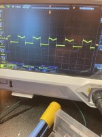
I removed the scope battery ground to avoid a short through the scope. Using the probe ground on Q101Pin3, U9pin7 has a clean square wave. Using probe ground on the battery (screw hole) U9pin7 has the pictured wave in post50.
How can Q101pin3 have any voltage on it with no HV lines attached? Something must be leaking it to BD-OUT.
There was approximately -0.67v on Q101 pin 3. I shorted out the HV terminals on the output side with a screwdriver. Q101pin3 fell to 0v. If I remove the HV short Q101pin3 comes immediately back up to -0.55v
I removed the scope battery ground to avoid a short through the scope. Using the probe ground on Q101Pin3, U9pin7 has a clean square wave. Using probe ground on the battery (screw hole) U9pin7 has the pictured wave in post50.
How can Q101pin3 have any voltage on it with no HV lines attached? Something must be leaking it to BD-OUT.
There are a couple of things that can cause voltage there.
The voltage isn't referenced to anything so it's floating which can make you see voltage.
If you measure across the rail caps, you're likely to see voltage building back after discharging, even with no power source. This is due to dielectric absorption of the capacitors.
Same ground point, check the drive on the gate leg of Q101.
Probe ground on q101pin3, Q101pin1 has -9.72vdc on it
U10 pin 1 has a 90khz square wave about 2v peak, 8vdc. U10pin5 has -9.72vdc. It’s as if u10pin5 is shorted to the -10v vdd
U10 pin 1 has a 90khz square wave about 2v peak, 8vdc. U10pin5 has -9.72vdc. It’s as if u10pin5 is shorted to the -10v vdd
What does the square wave look like if you use pin 2 of U10 as the reference?
Compare the resistance (no power applied) from pin 5 to pins 3 and 4 of U10 and U6.
Compare the resistance (no power applied) from pin 5 to pins 3 and 4 of U10 and U6.
I don't think U9 was at risk of damage. Recheck the amplitude on the input pad for U10.
If you didn't pull it to check it out of the circuit, do so before replacing it.
If you didn't pull it to check it out of the circuit, do so before replacing it.
Pulled out u10. Still about 2 ohms from pin5-4
Replaced it. When I ordered u17 for potential replacement I got basically all the silicon from rca up until the output fets. Bit wasteful of cash, like $60 but willing to splurge to avoid possibly repeated shipping time and cost
So… success. The U9pin7 flattened out and didn’t have the odd dip. Got hv jumper back in, removed u17 jumper… and we’re rocking. Full wave on output. Clean.
Should I do anything anything else while I’m in it like replace the bulk battery and hv caps? I originally found c59 and c60 vented. Did this likely happen from a failing u10 (or loose j105 bar jumper), or from age? If from age I’m tempted to change all the electrolytics.
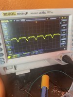
R44 still gets hot, even when I had the hv jumper removed. With jumper in and while testing scope on hv (at the diode legs) shows nothing until you turn time base way down (attached screenshot). Assuming normal?
Replaced it. When I ordered u17 for potential replacement I got basically all the silicon from rca up until the output fets. Bit wasteful of cash, like $60 but willing to splurge to avoid possibly repeated shipping time and cost
So… success. The U9pin7 flattened out and didn’t have the odd dip. Got hv jumper back in, removed u17 jumper… and we’re rocking. Full wave on output. Clean.
Should I do anything anything else while I’m in it like replace the bulk battery and hv caps? I originally found c59 and c60 vented. Did this likely happen from a failing u10 (or loose j105 bar jumper), or from age? If from age I’m tempted to change all the electrolytics.
R44 still gets hot, even when I had the hv jumper removed. With jumper in and while testing scope on hv (at the diode legs) shows nothing until you turn time base way down (attached screenshot). Assuming normal?
Troubleshooting methodically/logically is virtually always more successful than blindly replacing parts.
The broken jumper likely caused the caps to fail.
R44 is a large resistor because it's expected to get hot.
Blindly replacing caps is generally a waste of time and money.
What's the DC offset across the speaker terminals?
The broken jumper likely caused the caps to fail.
R44 is a large resistor because it's expected to get hot.
Blindly replacing caps is generally a waste of time and money.
What's the DC offset across the speaker terminals?
- Home
- General Interest
- Car Audio
- RF BD1000.1 repair