The resistor is large because it's expected to dissipate a lot of power (in the form of heat).
Yes, it's a snubber. The resistor can overheat (desolder itself) if there is a problem causing the transformer to produce more ringing than normal.
Yes, it's a snubber. The resistor can overheat (desolder itself) if there is a problem causing the transformer to produce more ringing than normal.
Yikes. Output on the scope is…. Not good. Only bottom half of the wave.
If it can pull the load low… that means something with the pmos outputs or drivers?
If it can pull the load low… that means something with the pmos outputs or drivers?
It could be in the drive circuit. The high offset on U17 was a concern. I'd troubleshoot without rail voltage.
To do that, desolder the rail wires (after discharging through a resistor) from the rectifier end of the wires.
Then use a jumper to short from pin 2 to pin 6 of U17.
Look at the input and the output of the various components to see if the output is right for the input.
To do that, desolder the rail wires (after discharging through a resistor) from the rectifier end of the wires.
Then use a jumper to short from pin 2 to pin 6 of U17.
Look at the input and the output of the various components to see if the output is right for the input.
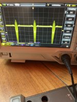
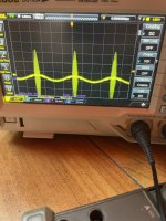
I’m suspecting u17. Here are traces of the output pin 6 and input pin 2.
No jumper yet, 50hz input
And what’s with all that noise at the peak of the wave? If I scope the input directly at the rca’s it’s there. If I remove the remote but leave the battery hooked up it’s fine the noise disappears.
No jumper yet, 50hz input
And what’s with all that noise at the peak of the wave? If I scope the input directly at the rca’s it’s there. If I remove the remote but leave the battery hooked up it’s fine the noise disappears.
Attachments
Amp is being fed by a lithium battery. Scope ground is on B- terminal. I put a probe on the second channel of the scope and clipped that lead to B- so I can use the first channel probe without the ground clip.
Do you agree on u17 being bad?
Do you agree on u17 being bad?
Not with the information you posted.
It's VERY odd that you have noise back to the RCAs. That would seem to be a setup problem.
U17 could possibly be bad but from what you posted earlier, it's OK. Why didn't you install the jumper? With an open feedback loop, very odd things can happen.
It's VERY odd that you have noise back to the RCAs. That would seem to be a setup problem.
U17 could possibly be bad but from what you posted earlier, it's OK. Why didn't you install the jumper? With an open feedback loop, very odd things can happen.
I’m still running a resistive load in the speaker terminals and the power supply red/black is still there. Nothing is open yet.
I figured with a full wave in and half wave out it was bad.
I figured with a full wave in and half wave out it was bad.
OK. I can't simulate every possible outcome for every fault. That's why I suggested the test as I did.
I was just starting at the beginning of the signal chain and testing up to that point before removing red/black. If after replacing u17 I still have a half wave on the output I’ll pull red/black and put in the jumper to keep working forward
The noise appears to be radiating and being picked up by everything. It’s at the rcas, at B+, at the vcc of u17
The noise appears to be radiating and being picked up by everything. It’s at the rcas, at B+, at the vcc of u17
I don't like or help with (blind) replacement of parts without a good reason.
Do you see the noise on the terminals of the battery?
Do you see the noise on the terminals of the battery?
With everything still intact, nothing removed or bypassed, can you think of another reason, besides u17 being bad, that it would have a full wave in but only half wave out?
Yes, the noise is on B+ (battery positive 4awg terminal) and goes away when the audio is turned off but amp still powered up.
Yes, the noise is on B+ (battery positive 4awg terminal) and goes away when the audio is turned off but amp still powered up.
Is the scope's main ground connected to the battery B+?
What if you use the ground wire on the scope probe you're using for testing?
Why didn't this show up as a problem earlier?
The problem could be virtually any component in the circuit, or simply part of your test setup. I can't/won't say U17 is defective with what you've posted.
What if you use the ground wire on the scope probe you're using for testing?
Why didn't this show up as a problem earlier?
The problem could be virtually any component in the circuit, or simply part of your test setup. I can't/won't say U17 is defective with what you've posted.
The scope has a common ground amongst all the 4 channels. CH2 scope probe ground is connected at B- 4awg terminal. The snapshots are from CH1. The ground lead on the scope is only 4” or so long, so it’s impossible to put it on B- terminal which is on one side of the board while I probe u17 that is on the opposite side. Unless I find a large enough ground for the alligator clip on the probe on that side of the board. Or maybe use two channels in differential mode.
When I first used the scope I only looked at speaker output terminals. That’s when I initially found the half wave. No noise was visible there, or very little to point it can’t be seen. I didn’t scope anything else at that point.
That’s when you gave the suggestion of troubleshooting with red/black removed and u17 jumpered. Before pulling the board back out of the heat sink to do so, I started probing more. That’s when I also found the half wave at u17 and the noise everywhere.
If there is a half wave on the u17 output doesn’t that need to be addressed first before troubleshooting the output stage drivers/fets?
Is it possible we are looking at different schematics? I’ve attached a portion of the one I’m referencing. U17 is the final opamp before the output stage splits off into its halves.
Attachments

If the noise is on everything from the RCAs to the terminals of the battery, it should have showed up on the output.
You don't need a long ground lead. The scope's main ground should be connected to the battery negative. The short ground lead can be (should be) connected to a ground very near U17. The nearest ground is pin 3 of U17. Do you get the odd noise using those TWO grounds?
You said PC# 3125. That's what I'm using. The amps of this type are very nearly identical. The 1500 is slightly different but you can even use that for most of the 1000w versions.
With the amp as is, U17 is responding to the performance/operation of EVERY component between the U17 output and the BD_OUT point on the output transistors. ANY defective part between those two points can make U17 behave strangely and it can react (at least) a few hundred thousand times a second. The output of U17 will typically look nothing like the output signal at the output terminals of the amp.
I apologize if this is dense or just plain stupid. But when you say “main” ground what do you mean? The only grounds available on the scope are on the probes which end in an alligator clip. There is no ground lug/screw on the back. There are two exposed metal contacts on the front meant for calibrating the probe compensation but I’ve never seen that ground used for typical measurement.
I have some skinny copper rod. I can cut a short piece and sharpen the end. This would allow the alligator clip to grab one end and the sharp end to get between things on the board that a blunt alligator clip can’t. Maybe heatshrink for insulation
I have some skinny copper rod. I can cut a short piece and sharpen the end. This would allow the alligator clip to grab one end and the sharp end to get between things on the board that a blunt alligator clip can’t. Maybe heatshrink for insulation
In the owner's manual, that bottom lug is ground. You can measure the resistance to the ground terminal of the power plug, to the BNC connectors of each channel.
I don't understand what you want to do with the rod.
I don't understand what you want to do with the rod.
Yes I assumed the test signal ground lug is the same as the probe bnc ground. I just never heard of it referred to as main ground or even used for anything other than calibration/compensation. So test signal ground to B- and probe ground to u17. Got it, will report back.
The probe ground is an alligator clip style. There’s no way to use that for in circuit measurement around a board this dense without shorting things out.
The probe ground is an alligator clip style. There’s no way to use that for in circuit measurement around a board this dense without shorting things out.
Solder a resistor lead or other small wire to pin 3 of U17 (cip to that) and see if you get a cleaner signal.
I don't know the terms used by every manufacturer for everything on every piece of equipment. That ground is likely spot-welded to the chassis/frame of the scope.
I don't know the terms used by every manufacturer for everything on every piece of equipment. That ground is likely spot-welded to the chassis/frame of the scope.
Perry with your ground scheme I did get a much cleaner signal.
The measurements were the same shape though. U17 input pin2 is a full wave approx 3.5v peak-peak centered at -2v. The output at pin 6 is a half wave (the negative half) centered at about +8v, with an 8v peak. The output appears to be only the negative rail.
The measurements were the same shape though. U17 input pin2 is a full wave approx 3.5v peak-peak centered at -2v. The output at pin 6 is a half wave (the negative half) centered at about +8v, with an 8v peak. The output appears to be only the negative rail.
- Home
- General Interest
- Car Audio
- RF BD1000.1 repair