Can you provide a photo image of the Hiface PCB? Also are you using the newer Crystal RX chips?
I've done some previous work on the boards & photos seen here: http://www.diyaudio.com/forums/digi...sb-spdif-24-192khz-asynch-12.html#post2020704
I'm not being specific about the SPDIF receiver chips being used.
Last edited:
Why ? I think this has a large bearing on your claims. The newer chips using 3V logic really might not like a 5V input.I'm not being specific about the SPDIF receiver chips being used.
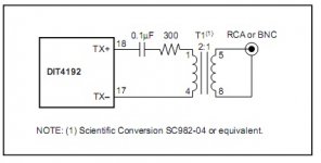
So only sometimes & not always as was stated! This is important information for anybody looking to properly their "properly designed" terminations. For instance what do you make of the Hiface SPDIF transmitter circuitsometimes it depends on what termation scheme is used. The most simple uses a direct connection to a 75 ohm others use DC blocks or transformers before the termination point.
Attachments
If the receiver works with the Hiface at a higher SPDIF signal of 2Vpp it should also work with the signal attenuated down to the standard SPDIF of 0.5Vpp, no?Why ? I think this has a large bearing on your claims. The newer chips using 3V logic really might not like a 5V input.
Anyway, this is about attenuating jitter on the cable!
Using a 2 to 1 with a primary source 300 ohms should be the proper 75 ohm output impedance. The transformer design itself should limit the BW. good rise and fall time are the HF and the LF is # turns and the core size depending on the max word length or the number of clock cycles without data transitions.
well the Rx chip has only so much isolation dB's between the digital section and the analog section. I suppose it's possible with a gigantic data input to have some feedthru to the anolog phase detector.
Should you not take the output impedance of the TX+ & TX- driver outputs into consideration in this?Using a 2 to 1 with a primary source 300 ohms should be the proper 75 ohm output impedance. The transformer design itself should limit the BW. good rise and fall time are the HF and the LF is # turns and the core size depending on the max word length or the number of clock cycles without data transitions.
Yes but the output fets have low Rds in the lower 10s of ohms. I'll check the data sheet to make sure
I calculate it about 18ohms (real impedance characteristic measurement may reveal more) so with above circuit it is mis-terminated by at least 18ohm? Add to this the cable impedance tolerance, plug & socket connections, etc. and we don't have anything like a properly terminated system end to end. Puts paid to the whole notion of properly terminated? How many circuits have you seen with proper termination, then?As I said before - it's certainly not just a DMM measurement & anybody suggesting such is badly mistaken!
Last edited:
well just as I assumed the Tx ouput fets have a spec'd Rds of around 13-20 ohms the HF impedance Z0 and output Tx pulse shape is mostably determined by the transformer itself rather than source termination resistor or the connecting cable at LF. here is a good white paper on this subject http://www.scientificonversion.com/AES1998.pdf
So are you saying that this 20ohms can be ignored? plus cable impedance tolerance can be ignored, plus the connectors impedance issues can be ignored? What do you reckon this might add up to in terms of total impedance mismatch?well just as I assumed the Tx ouput fets have a spec'd Rds of around 13-20 ohms the HF impedance Z0 and output Tx pulse shape is mostably determined by the transformer itself rather than source termination resistor or the connecting cable at LF. here is a good white paper on this subject http://www.scientificonversion.com/AES1998.pdf
No not ignored
It's just that the BW of the pulse XFMR is a lowpass with lowering Z with HF, so the total Z at low freq of many clock cycles would be the mismatch you are pointing out ie including the Tx Rds. but is in fact lower due to the transformer parasitics in parallel at the freq of one clock cycle.
It's just that the BW of the pulse XFMR is a lowpass with lowering Z with HF, so the total Z at low freq of many clock cycles would be the mismatch you are pointing out ie including the Tx Rds. but is in fact lower due to the transformer parasitics in parallel at the freq of one clock cycle.
not sure it's a simple Q with a complex answer. I think if you use "standard practices" and make you have bandwidths greater than the XFMR you are gold. If you could lower the Tx Rds it would be bad for that interface IMO.
I guess what I'm also getting at is that the claims that if systems were "properly terminated" by competent designers then there was no issue of reflections - which has been stated throughout this thread.
Now it's shown that "proper termination" isn't as simple as using a DMM but requires a lot more intelligence than this.
So let's first put to bed the notion that "proper termination " is commonly found in most SPDIF audio circuits - it is in fact a rare thing to find. Can we agree this?
Now, your statement that it is not as important as maybe it first seems is another issue altogether.
Last edited:
Hi
How about this.. can we agree that simply adding an attenuator may or may not improve jitter but it depends on specifics of the Rx and Tx circuit/s used since most importantly "Any digital audio receiver IC has finite dynamic range and CMRR. Low level, unbalanced signals, (e.g. SPDIF from a weak source on a lossy cable) will increase the error rate and jitter since the receiver has less margin and interference rejection. Astep-up transformer can increase the signal voltage level, improving both receiver performance and common-mode rejection."
How about this.. can we agree that simply adding an attenuator may or may not improve jitter but it depends on specifics of the Rx and Tx circuit/s used since most importantly "Any digital audio receiver IC has finite dynamic range and CMRR. Low level, unbalanced signals, (e.g. SPDIF from a weak source on a lossy cable) will increase the error rate and jitter since the receiver has less margin and interference rejection. Astep-up transformer can increase the signal voltage level, improving both receiver performance and common-mode rejection."
I guess what I'm also getting at is that the claims that if systems were "properly terminated" by competent designers then there was no issue of reflections - which has been stated throughout this thread.
And the conclusion remains that this is true.
Good paper Infinia, I hadn't seen it.
I'd like to point out that all the SPDIF receiver ICs whose datasheets I read (and I've read enough to be representative) show CONSUMER application circuits with 75R resistive termination. AES/EBU professional inputs are shown with transformers, but not consumer. This doesn't mean that there are NO consumer devices with transformers out there, but that's not really what I was suggesting anyway. The large majority of owners will be able to measure the termination with a DMM.
The only proper way to prove anything is using BER test set. The next best is eye diagram plots or phase noise plots. It would be more helpful to show pseudo eye diagrams using a digital sampling scope. Agilent and Tek have excellent tutorials on this.
This is absolutely correct, and is where I should have started my objections to the 'evidence' being presented, and is undoubtedly where I would have ended up once my irritation with the whole issue had subsided sufficiently to allow me to think clearly. As it was I was simply reacting to the obvious flaws in what was being presented.
The paper suggests that jitter due to common-mode noise can be usefully reduced by the use of a transformer at the receive end (in addition to that at the transmit end). It makes no mention of mismatching as a problem, however, and the techniques employed for matching are absolutely conventional. The complete absence of references to mismatching and reflections suggests that this is again, in the case of transformer-terminated receivers, a complete non-issue.
simply adding an attenuator may or may not improve jitter but it depends on specifics of the Rx and Tx circuit/s used since most importantly "Any digital audio receiver IC has finite dynamic range and CMRR. Low level, unbalanced signals, (e.g. SPDIF from a weak source on a lossy cable) will increase the error rate and jitter since the receiver has less margin and interference rejection.
Infinia, adding an attenuator might improve jitter if there were mismatching and there were excess signal available, but no evidence has been produced to suggest that mismatching is commnplace or significant.
jkeny, you deserve some congratulation anyway for persisting with this issue to the extent that you have, otherwise I wouldn't have had this paper called to my attention.
The fact remains that you relied on evidence which you did not understand to reveal nothing about the subject, and you propagated a solution to a problem which has not been demonstrated to exist, which 'solution' may actually create problems for the unwary.
w
Last edited:
Hi
How about this.. can we agree that simply adding an attenuator may or may not improve jitter but it depends on specifics of the Rx and Tx circuit/s used since most importantly "Any digital audio receiver IC has finite dynamic range and CMRR. Low level, unbalanced signals, (e.g. SPDIF from a weak source on a lossy cable) will increase the error rate and jitter since the receiver has less margin and interference rejection. Astep-up transformer can increase the signal voltage level, improving both receiver performance and common-mode rejection."
Trying to deflect from the point that I have shown this circuit is not" proper termination" will not work - wakibaki thinks he knows everything & so there is no hope for him but what's stopping you from admitting that you hadn't considered the output impedance characteristics of the drivers in consideration of the 75R impedance? You simply don't know what level of mismatch will cause a problem, do you!
Hi
Lousy pulse transformers maybe tamed somewhat using an attenuator but using them is potentially hazardous to the S/N ratio at the Rx end, Given the choice I would pick a larger signal over a pretty picture of a short duration data signal. It's all a balancing act.
Common mode interference is the real killer, anyone spending anytime interfacing single ended connections from noisy PCs to quiet analog gear esp. with an earth ground knows about this. Optical interfaces or transformers at both ends with electrostatic shields or better yet fully differential interfaces ie pro-sound are the solutions.
You simply don't know what level of mismatch will cause a problem, do you!
well I do know SPDIF mismatched impedance induced jitter is probably number 20 of importance on a list of other things that can affect jitter to a greater degree.
Impedance mismatch is not a pass/ fail number. It depends on many other factors related to the total link budget and how low your BER target is. jkeny you are lost by focusing just on this silly attenuator scheme. I guess you will make me sorry I helped you look at the bigger picture.
- Status
- Not open for further replies.
- Home
- Source & Line
- Digital Source
- RF Attenuators = Jitter Reducers