We had to go to considerable lengths with very fast rise times, a very expensive oscilloscope and long, long cables for a university lab demonstration of reflection in digital systems,
Well that's interesting to me. Because reflections on an analog 75 ohm video line are easy to see. Be it NTSC, PAL, VGA, XGA, etc. Even a bad crimp or loose BNC can cause visible reflections. (I'm a video engineer, so have to deal with this often).
Don't know if reflections like that would cause jitter or other digital errors, I would hope the receiver chips are more immune to reflections than analog video. You know - what's the threshold before there is a timing error?
Panomaniac,
There is nothing digital in clock recovery from the SPDIF data. It's an analog
process. Data extraction is digital, with high enough safety margins to achieve very low error levels even with a noisy transmission channel. There are no data errors in SPDIF, in normal circumstances.
But there is ample phase noise in the recovered clock. The "classic" Crystal receivers are using an analog PLL, phase detector+VCO. They have a PLL loop filter cutoff frequency at around 20kHz. With some peaking included.
Latest receivers are presumedly better, using at least some vcxo with much lower loop filter corner, though it would be nice to be able to see independent tests, like those what John W. had been doing at diyhifi.org in the past.
Ciao, George
For those who are still not bored.
Previously I was accused (by wakibaki) of not being able to demonstrate a possible connection between reflections and jitter in a transmission line. I would quote:
I was responding that I suppose the effect to be very small, and difficult to show, at around 10-100picosecs. Because I was trying to create / show something close to "normal life" situation in my setup, so the reflections were / are not big.
So ok, here it is a first try at this problem.
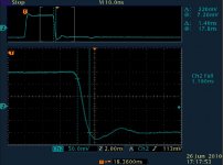
I'm again using the same 'HP generator -line-BNC tee- termination' experimental setup, with the BNC tee connected to the oscilloscope 1Mohm input.
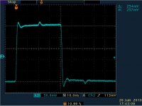
The generator is set to produce a pulse, edges are ~1.2ns, variable width from 5 to 30nsec. The test cable has an electrical length of 10ns, so the reflection shows up ~20ns after the starting edge.
It looks like this - very similar as in the previous attenuator tests.
Because of the continuous accusations of wakibaki, I would report here again the amplitude values from the previous (attenuators) setup:
It was at
pulse height 680mV, reflection peak 40mV. ratio: 5,88%
Now from these graphs the
pulse height is: 254mV, reflection peak is 15mV. ratio: 5,88%
Previously I was accused (by wakibaki) of not being able to demonstrate a possible connection between reflections and jitter in a transmission line. I would quote:
What I want to see is the SUPERPOSITION (your emphasis) of the reflection causing appreciable movement in the distance between the rising and falling edges, before and after attenuation, as measured with a cursor. I also need to see that this variation is greater than the intrinsic jitter generated by the transmitter.
You will not be able to demonstrate this. If you could do so, you would have done so already. Your whole case is built on a preconception which is distorting your interpretation of the evidence.
I was responding that I suppose the effect to be very small, and difficult to show, at around 10-100picosecs. Because I was trying to create / show something close to "normal life" situation in my setup, so the reflections were / are not big.
So ok, here it is a first try at this problem.
I'm again using the same 'HP generator -line-BNC tee- termination' experimental setup, with the BNC tee connected to the oscilloscope 1Mohm input.
The generator is set to produce a pulse, edges are ~1.2ns, variable width from 5 to 30nsec. The test cable has an electrical length of 10ns, so the reflection shows up ~20ns after the starting edge.
It looks like this - very similar as in the previous attenuator tests.
Because of the continuous accusations of wakibaki, I would report here again the amplitude values from the previous (attenuators) setup:
It was at
pulse height 680mV, reflection peak 40mV. ratio: 5,88%
Now from these graphs the
pulse height is: 254mV, reflection peak is 15mV. ratio: 5,88%
Attachments

I was thinking that a possible demonstration could be the following:
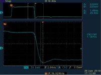
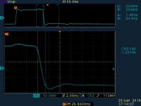
The scope is always triggered on the pulse rising edge. This rising edge is exciting the reflection, which will arrive always at a fixed 20ns.
Then the pulse falling edge is varied, it is "scanning" a time interval covering /including the reflection.
The object under "suspicion" is this falling edge. As it is moving along, at a certain point it will be in coincidence with the reflection. If one can observe nothing, no deformations during this transition from before to after reflection, then wakibaki is right.
Another important point is that this edge should be constant shape, uniform in the different other points where there is no perturbation.
For control, I'm using cursors plus the built in falling edge measurement, watch for the "delta" cursor readings, and the fall time.
In the pics I'm moving backwards, 30nsec, 28nsec, reflection, finally one point before the reflection, 18nsec
Attachments
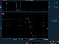
I can assure You, the effect is real, I'm able to repeat it, but also, if one observes the falling edge, it's visibly changing shape. The built in scope measurement is quite an objective observer, too.
Both the cursors and the fall time give a ~100psec difference at the coincidence point.
Consider that: I'm using a very fast edge, which is kind of a "best case" to avoid this kind of influence;
but also, this edge is very close in speed to the "real case" highface driver speed;
the reflection is principally generated by the BNC tee, which itself is quite close to an RCA connector, (TDR response) as I had shown it in the diyhifi.org thread.
So I would consider this demonstration to be a very "lifelike" simulation for SPDIF.
Previously I had shown that with the real SPDIF driver, the Hiface, I had seen this coincident reflection by simply putting on one of my real, home use SPDIF cables.
Ciao, George

An ungracious retreat, I see without even a thank you to Joseph. I, for one, would like to extend my thanks & respect to Joe for the obvious work he has put into this.
Retreat bedamned, the claims were made on evidence which didn't exist.
I'm simply not prepared to bandy words any further.
w
I'm simply not prepared to bandy words any further.
w
Maybe what's needed is a third party who is experienced enough to interpret the plots as evidence of reflections on the falling edge of the signal - otherwise it just appears as diametric viewpoints that few enough of the readers are able to judge the veracity of for themselves.
What I can judge though is Joseph's trojan efforts to satisfy your increasingly demanding requirements for proof & your rejection of these at every turn, usually with a different requirement/claim being introduced. Firstly you denied the whole concept of termination problems, then you rejected the idea of reflections on SPDIF lines, then you suggested that there never were any plots or measurements taken, then you wanted to be shown the reflections causing the timing issues at the rising or falling edges & finally now you leave when all this is apparently done.
You started all this by accusing me of spreading mis-information & casting a slur on design engineers which you seemed to number yourself among & were defending - you sir, are doing more damage to your profession (if you are representative of them) than ever I could (not that I ever intended any slur)!
Last edited:
Panomaniac,
There is nothing digital in clock recovery from the SPDIF data. It's an analog
process. Data extraction is digital, with high enough safety margins to achieve very low error levels even with a noisy transmission channel. There are no data errors in SPDIF, in normal circumstances.
But there is ample phase noise in the recovered clock. The "classic" Crystal receivers are using an analog PLL, phase detector+VCO. They have a PLL loop filter cutoff frequency at around 20kHz. With some peaking included.
Latest receivers are presumedly better, using at least some vcxo with much lower loop filter corner, though it would be nice to be able to see independent tests, like those what John W. had been doing at diyhifi.org in the past.
Ciao, George
But the interface here is digital! The extraction of the clock from the random data stream is the only analog part.
BTW your single shot Oscope plots of random data don't prove anything without showing a test setup for starters. The only proper way to prove anything is using BER test set. The next best is eye diagram plots or phase noise plots. It would be more helpful to show pseudo eye diagrams using a digital sampling scope. Agilent and Tek have excellent tutorials on this.
The latest receivers use 3 Volt instead of 5V logic, so by your measurements wouldn't they be worse. I think some folks look at digital waveforms as beholden to some time domain fidelity of an amplifier square wave test. LOL
There is nothing digital in clock recovery from the SPDIF data. It's an analog process.
Ah yes, I see what you mean. Clock recovery is analog. Thanks. But.... (see above)
I'm not sure I understand what you mean here. Is the sensing of the transition point an analogue sensing of the crossing?But the interface here is digital! The extraction of the clock from the random data stream is the only analog part.
The test setup was shown over on Diyhifi.orgBTW your single shot Oscope plots of random data don't prove anything without showing a test setup for starters.
It's a pity you didn't get here earlier when wakibaki was making his demands for different measurements as proof of the effect of reflections on the transitions - are you saying that this was a fool's errand?The only proper way to prove anything is using BER test set. The next best is eye diagram plots or phase noise plots. It would be more helpful to show pseudo eye diagrams using a digital sampling scope. Agilent and Tek have excellent tutorials on this.
The latest receivers use 3 Volt instead of 5V logic, so by your measurements wouldn't they be worse. I think some folks look at digital waveforms as beholden to some time domain fidelity of an amplifier square wave test. LOL
Hi
I don't have a horse in this race, but I have designed Gb clock recovery circuits though.
The contribution of the SPdif interface to jitter of the Tx and Rx link budget should be very very low and is generally robust, given proper terminations and reasonable care on the choice of RCA cables. I'm just a little skeptical of the claim of adding an attenuator will give better performance as a general rule. I'm not making any demands on testing, If you have the experience you will know what kind of testing is involved,
If we could see the circuits used on both ends of your setup... then we might see the light ie your claim may have technical merit otherwise it's just another subjective experience in the dark. LOL
I understand your position & I'm not trying to prove anything other than to introduce the idea for experimenting by others & maybe reporting their subjective experiences - if these turn out to be better sounding, I don't particularly care to prove how this operates - we are after all interested in better reproduction of a recorded event.
I started this thread with this
And I was & still am happy to hear reports of people's subjective experience of this but this thread took a direction I didn't like when I got attacked for spreading mis-information & slurring a profession!
I started this thread with this
These are premises based on how the attenuators work - real world results may be different although I have tested a BNC to RCA adaptor with & without one of these attenuators & the sound was noticeably smoother & without edge with the attenuator in-line.
And I was & still am happy to hear reports of people's subjective experience of this but this thread took a direction I didn't like when I got attacked for spreading mis-information & slurring a profession!
Last edited:
If you want real jitter reduction, I'd suggest looking at reducing the Rx PLL analog loop BW. I'm thinking... because the Hiface is a Tx with a free running clock, it may be improved considerably by a little custom tuning of the PLL to filter out the Tx jitter. If there is any other room for improvement it would be interesting to see how the Hiface link the incoming USB data to their master clock.
Yes, there are lot's of good, if not better suggestions for reducing jitter BUT all require much more work than clicking on an attenuator - this was a quick (2 sec), cheap ($12) experiment that a number of people have found & could find to be of benefit on their Hiface, that's all, really!
The Hiface has a separate 24MHz clock feeding the Cypress USB receiver - completely separate to the 22.XXX & 24.XXX audio clocks
The Hiface has a separate 24MHz clock feeding the Cypress USB receiver - completely separate to the 22.XXX & 24.XXX audio clocks
Last edited:
Can you provide a photo image of the Hiface PCB? Also are you using the newer Crystal RX chips?
Hi
I don't have a horse in this race, but I have designed Gb clock recovery circuits though.
The contribution of the SPdif interface to jitter of the Tx and Rx link budget should be very very low and is generally robust, given proper terminations and reasonable care on the choice of RCA cables. I'm just a little skeptical of the claim of adding an attenuator will give better performance as a general rule. I'm not making any demands on testing, If you have the experience you will know what kind of testing is involved,
If we could see the circuits used on both ends of your setup... then we might see the light ie your claim may have technical merit otherwise it's just another subjective experience in the dark. LOL
Just to address some other issues:
- can you please confirm, for the sake of correcting mis-information, that the termination cannot simple be measured with a DMM, as has bee claimed here?
- the set-up is not mine so I won't try to explain but it involves a TDR
can you please confirm, for the sake of correcting mis-information, that the termination cannot simple be measured with a DMM, as has bee claimed here?
sometimes it depends on what termation scheme is used. The most simple uses a direct connection to a 75 ohm others use DC blocks or transformers before the termination point.
- Status
- Not open for further replies.
- Home
- Source & Line
- Digital Source
- RF Attenuators = Jitter Reducers