Thanks again,as soon as this will be alive we can try 3 options.😉OK, for 2SK146:
- R6, R10 = 22R
- C2 = 100pF
Measured performance at 1 KHz is going to be roughly the same, distortion at 20KHz will be roughly doubled/tripled. Although, it will be interesting to know your listening impressions, as well as its performance from the noise point of view.
Regards.
Thimios
Hi Valery, for the AX-DELUXE i have for C11 10pf instead of 8p2
for C13 1.5pf instead of 1pf
R22,R23 560k instead of 680k
Are these values so critical?
Is it needed a heatsink for the VAS at +/-50V?
for C13 1.5pf instead of 1pf
R22,R23 560k instead of 680k
Are these values so critical?
Is it needed a heatsink for the VAS at +/-50V?
Last edited:
Thanks!Hi Thimios, those values are fine.
Cheers,
Valery
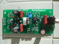
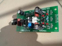
Small progress.A mix of smd&th parts.😀
Attachments
Last edited:
Thanks!
Small progress.A mix of smd&trh parts.😀
Huh! Cool ))
SMD pads are convenient enough for soldering TH parts on the test boards.
What is the recommendation for the red leds,and what about the VAS heatsink at +/-50V?Is it necessary?
Last edited:
I normally use pretty standard 3mm / 5mm Kingbright LEDs.
Small snap-on or plate heatsink is recommended for better VAS current stability.
Small snap-on or plate heatsink is recommended for better VAS current stability.
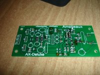
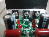
Just a little before the finalizing!
Attachments
Last edited:
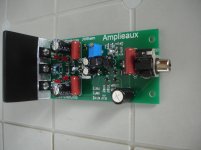
AX-Deluxe
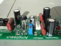
Now is completed!
Maybe i can test this during this Weekend.
Now is completed!
Maybe i can test this during this Weekend.
Attachments
Last edited:
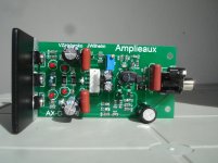
AX-Deluxe
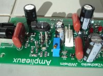
More photos.
The official site: High Fidelity Audio Equipment | Canada | VIRTUAL ZERO AUDIO
More photos.
The official site: High Fidelity Audio Equipment | Canada | VIRTUAL ZERO AUDIO
Attachments


Can someone point me to the Shunt Power Supply schematic which was posted by vzaichenko in one of his threads. Thanks in advance.
Can someone point me to the Shunt Power Supply schematic which was posted by vzaichenko in one of his threads. Thanks in advance.
CF-FET V2.0 front-end - going high-tech (SMD)
Can someone point me to the Shunt Power Supply schematic which was posted by vzaichenko in one of his threads. Thanks in advance.
Here we go:
http://www.diyaudio.com/forums/solid-state/270402-cf-fet-v2-0-front-tech-smd-11.html#post4299722
Cheers,
Valley
Thank you very much, jwilhelm and vzaichenko. I read through that whole thread again. Such an inspiring read.
I want to use the Shuntie to power a front end which draws 32mA with rails of +-32 to 35 volts DC. I will try without changing any values. Thanks again.
I want to use the Shuntie to power a front end which draws 32mA with rails of +-32 to 35 volts DC. I will try without changing any values. Thanks again.
Thank you very much, jwilhelm and vzaichenko. I read through that whole thread again. Such an inspiring read.
I want to use the Shuntie to power a front end which draws 32mA with rails of +-32 to 35 volts DC. I will try without changing any values. Thanks again.
No problem - with 32mA draw it's going to run just fine.
You have to reserve some voltage to drop at the series resistors.
In my case, I had 70V DC in -> 50V DC out.
Cheers,
Valery
Oh, that sounds good. Vzaichenko, what is the minimum voltage drop I can get away with and what then would be the value of the series Resistor?
You need to have the current through the MOSFET to be at least the same, as the one, drawn by your circuit, loading it.
In this case:
Iinput = Imosfet + Iload -> 64mA = 32mA + 32mA;
Series resistor value:
R = Vdrop / Iinput;
Series resistor power rating:
P = Vdrop * Iinput;
Cheers,
Valery
In this case:
Iinput = Imosfet + Iload -> 64mA = 32mA + 32mA;
Series resistor value:
R = Vdrop / Iinput;
Series resistor power rating:
P = Vdrop * Iinput;
Cheers,
Valery
- Home
- Amplifiers
- Solid State
- Revisiting some "old" ideas from 1970's - IPS, OPS