Hmm... I have been using 80mA bias on my VHeX+ would it have lower THD following this process? Use 10R safety resistors during adjustment can save from Big Bang.
No, for VHex+ 80mA is good. Different technology 😉
Valery,my bad English....please can you give me an arithmetic example(more analytical)?Yes.
First, set the bias with no signal to 65-70mA per pair.
Then, give it stable 1KHz and rotate the clamping spreader's trimmer from some middle position (no clamping) to position, when it just starts clamping.
Optimum (lowest THD) is just in the beginning of clamping.
But do it slowly and carefully, monitoring the bias all the time.
If you quickly set the clamping to some high position, you may have a big bang (current rail to rail shoot-through).
Valery,my bad English....please can you give me an arithmetic example(more analytical)?
I think, this one is the best one I wrote so far ))
Again, 2 main parts of setup (DMM is connected to emitter resistors all the time, clamping trimmer around the middle position):
1) NO SIGNAL - set the bias to 65-70mA; wait until the heatsink is warm, adjust if necessary.
2) 1KHz SIGNAL , say, 10V RMS at the output. Now you're working with the 2-nd spreader, set initially to the middle position. You will see some 150mV (or whatever you see) on your DMM. Rotate it slowly until you see the voltage growing to some +5mV. The optimal clamping operation point is somewhere between the initial value and initial +5mV one.
Attachments
Use 10R safety resistors during adjustment can save from Big Bang.
Having resistance in series with the supplies isn't a safe way to adjust bias. Rail voltage will drop causing an extremely high bias setting. When connecting the supply properly after, bias will be dangerously high.
We keep having to repeat this message. But they won't listen/read.Having resistance in series with the supplies isn't a safe way to adjust bias. Rail voltage will drop causing an extremely high bias setting. When connecting the supply properly after, bias will be dangerously high.
Yes clear enough,pdf say Dummy load is connected at all times ?
Assuming you've got zero offset at the output, it doesn't influence the "no signal" bias setting. However, during "1KHz signal" clamping setting, it must be there, otherwise you will just not see any clamping.
Good explanation!Assuming you've got zero offset at the output, it doesn't influence the "no signal" bias setting. However, during "1KHz signal" clamping setting, it must be there, otherwise you will just not see any clamping.
Some previous testing bias with and without load seeing no difference 😉
Last edited:
Having resistance in series with the supplies isn't a safe way to adjust bias. Rail voltage will drop causing an extremely high bias setting. When connecting the supply properly after, bias will be dangerously high.
Yes. Safety resistors help in case of the 1-st power on. As soon an we see the amp is stable, no surprises - all the rest has to be set with the normal full rails.
Good explanation!
Some previous testing bias with and without load seeing no difference 😉
Right. Zero offset at the output = zero current through the load. Meaning - it doesn't matter if it's there or not ))
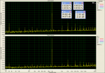
Right Mark test
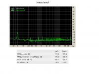
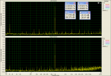
Also looking good, assuming certain sound card limitations 😉
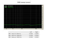
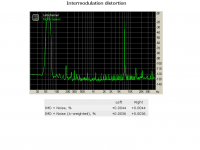
Nice IMD. I normally measure 14+15KHz, but it's low in any case.
Zero offset at the output+zero input signal=zero output voltage.Right. Zero offset at the output = zero current through the load. Meaning - it doesn't matter if it's there or not ))
Zero output voltage=zero current through the load.Meaning-it doesn't matter if it's there or not😉😉
Also looking good, assuming certain sound card limitations
Yes i wish to have something better

Last edited:
Having resistance in series with the supplies isn't a safe way to adjust bias. Rail voltage will drop causing an extremely high bias setting. When connecting the supply properly after, bias will be dangerously high.
I mean this will get it close - then do final adjust without the resistor. It's to keep me from blowing the outputs with an overzealous trim pot movement if I don't know what to expect. But for setting bias circa 100mA, without the resistor its maybe 150mA not dangerous by any means.
One of the nice thingsabout these Sanken output devices is an overzealous adjustment won't hurt them. Valery managed to black out his apartment with his without hurting an output.I mean this will get it close - then do final adjust without the resistor. It's to keep me from blowing the outputs with an overzealous trim pot movement if I don't know what to expect. But for setting bias circa 100mA, without the resistor its maybe 150mA not dangerous by any means.
One of the nice thingsabout these Sanken output devices is an overzealous adjustment won't hurt them. Valery managed to black out his apartment with his without hurting an output.
Yep. I love MT-200 Sankens. Besides their quality-related advantages, they are incredibly robust. I had a nasty high-swing oscillation in the front-end on a test bench the other day because of the compensation capacitor failure. Some other OPS could easily die at this situation. Not NS-OPS. After a few seconds, while I was still surprised with the whole thing, I've lost the mains power in the whole apartment 😱 Output transistors got hot, but did not get any damage. After fixing the fuse in the apartment distribution box and the capacitor in the front-end, everything worked nicely, as it always did 😀
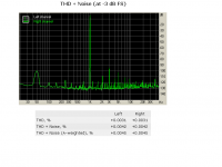
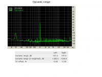
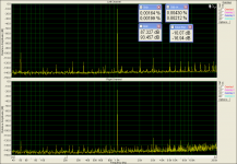
Bias and clamping readjusted and amplifier was tested again.
Now an even lower distortion level measured.
Now an even lower distortion level measured.
Attachments

Last edited:
Right - now overall level of distortion is even lower, slightly increasing at higher power - meaning, the bias is good 😎
slightly increasing at higher power - meaning, the bias is good
This is a question that i want to ask.
What is the point that you see and understand that the previous measurements has been taken with an under biased amplifier?
This is a question that i want to ask.
What is the point that you see and understand that the previous measurements has been taken with an under biased amplifier?
slightly increasing at higher power - meaning, the bias is good
This is a question that i want to ask.
What is the point that you see and understand that the previous measurements has been taken with an under biased amplifier?
Thi is valid for class AB output stages.
Imagine, you measure THD at relatively high output swing - say, 20V RMS (50W @ 8 ohm).
In case your OPS is under-biased, you will have some crossover distortion, but it's pretty much "masked" by the high-level base frequency tone.
Now, measure THD at 2.8V RMS at the output (1W @ 8 ohm). Crossover distortion stays roughly the same, but the level of the base frequency is much lower - THD value increases.
In correctly-biased OPS, crossover distortion's influence on overall THD is lower, than influence of the other sources' of distortion. In this case - lower swing -> lower THD.
- Home
- Amplifiers
- Solid State
- Revisiting some "old" ideas from 1970's - IPS, OPS