Then it was "in the very beginning" and now it's become "in the post #408"
Clarifying once again:
- DC2, initial idea of the basic complimentary differential configuration, with reference to Sansui engineers' article, is mentioned in the very beginning;
- VERTICAL is my particular front-end design, based on that idea, presented in the post #408 along with the pictures, measurements and comments.
I think, in the minds of many people, involved in audio engineering, the word "vertical" is very much related to the word "MOSFET" 😀
Not in this case 😉 Nothing to do with MOSFETs 😛
For those, who'd like more structured presentation - see my website, following the link below (in my signature).
I sim Vertical IPS with 3EF OPS. But I got low VAS current. I change R17 and R18 to get 5,8mA VAS current. I do not use C13 and C14.
It is the lowest THD of CFA amp that I ever sim. 😎
I sim Vertical IPS with 3EF OPS. But I got low VAS current. I change R17 and R18 to get 5,8mA VAS current. I do not use C13 and C14.
It is the lowest THD of CFA amp that I ever sim. 😎
It's very linear open loop and fast enough at the same time 😎
Should a zobel network be added to the output?
It can be added right at the output terminal, however with my speakers the amp works perfectly as is.
I've always meant to add one to the speaker relay for the protection board, but keep forgetting about it.
Can you say about a practical way to see if a speaker or speaker set can work in safe conditions without zobel added to an amplifier?It can be added right at the output terminal, however with my speakers the amp works perfectly as is.
Can you say about a practical way to see if a speaker or speaker set can work in safe conditions without zobel added to an amplifier?
In fact, Zobel network helps to somewhat linearise the speaker impedance. So, 2 considerations:
1) If you know, your speaker's impedance is linear enough and high enough for your amp - then you're safe;
2) If your amp has got high current capability at the output, so that, say 2 ohm impedance at some frequency does not hurt - then you're also safe.
NS-OPS is able to deliver some 30A when required, handling even difficult speakers. Although, a small inductor at the output never hurts, isolating the output from the high capacitive loads at the high frequencies.
See a good material on Zobel network here:
Passive Crossover Network Design
Do you know what changes would need to be made to run at +-70V rails? It's seems a waste running 3 pairs of Sankens at 50.
Do you know what changes would need to be made to run at +-70V rails? It's seems a waste running 3 pairs of Sankens at 50.
In fact, no changes required 🙂 I have initially calculated all the values for +/-70V DC and then just ran them at +/-52V, as I had this PSU in hand.
However, let me check some values once again, just to be on a safe side.
At +/-70V rails, you will end up with some 250W RMS output power @ 8 ohm... if the heatsinks will be good enough 😉
I've had mine playing all day with the heatsinks laying with the fins flat on my coffee table and they're just warm. These things run almost as cool as the CFA-CFPx2. My stupid cat's only tripped the protection once.
I've had mine playing all day with the heatsinks laying with the fins flat on my coffee table and they're just warm. These things run almost as cool as the CFA-CFPx2. My stupid cat's only tripped the protection once.
Same thing here, but they become hotter after one hour of testing at 50W with dummy load, especially with a square wave signal - in this case, it's even more than 50W))
Although, in normal home listening conditions - nothing to worry about, even at high volumes 😎
That clarifies the situation completely.Clarifying once again:
- DC2, initial idea of the basic complimentary differential configuration, with reference to Sansui engineers' article, is mentioned in the very beginning;
- VERTICAL is my particular front-end design, based on that idea, presented in the post #408 along with the pictures, measurements and comments.
Now go and add an index in post1 with some comment and a link to post408
Last edited:
Can you say about a practical way to see if a speaker or speaker set can work in safe conditions without zobel added to an amplifier?
A speaker Zobel is different from an amplifier's output Zobel.In fact, Zobel network helps to somewhat linearise the speaker impedance. So, 2 considerations:
1) If you know, your speaker's impedance is linear enough and high enough for your amp - then you're safe;
2) If your amp has got high current capability at the output, so that, say 2 ohm impedance at some frequency does not hurt - then you're also safe.
NS-OPS is able to deliver some 30A when required, handling even difficult speakers. Although, a small inductor at the output never hurts, isolating the output from the high capacitive loads at the high frequencies.
See a good material on Zobel network here:
Passive Crossover Network Design
A speaker Zobel is there to "flatten" the speaker's impedance and help the speaker to become closer to a flat frequency response.
This speaker Zobel would be located at the speaker and designed by the speaker designer.
An amplifier output Zobel is there to provide a high frequency load that helps maintain the amplifier's stability margins. This is at the amplifier output devices and is designed by the amplifier designer.
Don't mix them up !
Valery, nice design! A few questions base on the schematic you posted:Meanwhile, I have tested my current-driven TIS (AmpliWire VFA). Terry did it earlier, I just wanted to have more detailed measurements.
What's the purpose of C7 (the 100nF on the LTP CCS)?
Is it a theoretical element or you tested it with measurements?
The similar to R36/36: are they there due to some traditions or it's performing better this way?
Thanks!
Valery, nice design! A few questions base on the schematic you posted:
What's the purpose of C7 (the 100nF on the LTP CCS)?
Is it a theoretical element or you tested it with measurements?
The similar to R36/36: are they there due to some traditions or it's performing better this way?
Thanks!
Hi Cortez,
Those are the things I normally use because of the following reasons:
- C7 is simply an HF shunt for the CCS voltage reference, providing additional filtering of the whatever artefacts, present in the rails.
- R35/36 - they just help to slightly "normalize" the OPS input impedance, increasing linearity. I did not research their influence in this particular design, but in the other one, long time ago, they really reduced some distortion.
I use those things as a "good practice" now ))
Cheers,
Valery
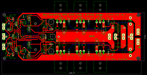
Last week, Marc (idefixes) has slightly re-designed the layout for the output devices NJW3281/1302, it also has 90 degrees drivers orientation, in one line, so that they can share the same aluminium plate - in this case, PCB length is only 220mm. So, for the future builders, this option is also available.
Cheers,
Valery
Here is the NS8ops variant Valery talked....220mm length board for TO264/TO-3P. Following Valery advice there is 6 more holes for more classical emitter resistors than MCP71...I will let chinese new year time going over and send files to board house.
Marc
Attachments
Last edited:
On the Vertical input, will lowering the value of R1 to 47k cause any issues? I'd like to figure out the open input buzz. It's there when I turn my pre-amp off.
- Home
- Amplifiers
- Solid State
- Revisiting some "old" ideas from 1970's - IPS, OPS