On the Vertical input, will lowering the value of R1 to 47k cause any issues? I'd like to figure out the open input buzz. It's there when I turn my pre-amp off.
No problem, you can go even lower, as far as your preamp can handle the lower input impedance. You will also need to lower R3 to allow the DC handling the offset. Input impedance practically equals Zin = 1 / (1 / R1 + 1 / R3)
By the way, my prototype has got no hum when the preamp is off. There is just some hum when the input is completely open.
Last edited:
No problem, you can go even lower, as far as your preamp can handle the lower input impedance. You will also need to lower R3 to allow the DC handling the offset. Input impedance practically equals Zin = 1 / (1 / R1 + 1 / R3)
By the way, my prototype has got no hum when the preamp is off. There is just some hum when the input is completely open.
My preamp must leave the output floating when it shut's down. I need to get back at the Pitchfork Preamp soon.
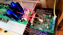
Soldered the 2-nd channel of the VERTICAL front-end. Just exchanged with the 1-st one - works perfectly right away. Singing on a test bench with the main speakers now.
Jeff, I did some testing with the input disconnected - there is a little bit of noise, but very minor one. I recognize the difference only when my ear is close enough to the speaker. Then, when I connect the pre-amp (being off), it becomes silent, with barely recognizable hiss, and then after powering the pre-amp on, it's not even silence - it's nothing 😛
Pre-amp is an Onkyo digital processor in my case.
I'm interested in the nature of the open-input noise in your case - is it some EMF, or just coming from the rails somehow?
Attachments
Mine is connected to a Nad preamp and 102 db/W speakers. If there's any noise anywhere, you hear it through these speakers quite well.
I've got a pair of monoblock Slewmonsters I need to get finished. I'll get back into these after them.
I've got a pair of monoblock Slewmonsters I need to get finished. I'll get back into these after them.
About the NS-OPS: (Or is there a better thread I should use to this topic?)
It's good even for BJTs and FETs as well?
Does somebody have some experience with both?
It's good even for BJTs and FETs as well?
Does somebody have some experience with both?
It's good even for BJTs and FETs as well?
Probably yes. "The Hitachi HMA-7500 Mk2 (MOSFET outputs) had the ‘super linear’ feature, and also a ‘distortion servo’ which appears to be some kind of error-correction. It is claimed that the latter reduces output-stage distortion by a factor of three. The HMA-9500 Mk2 (1980) used a ‘super linear’ nonswitching circuit in a different form." - Douglas Self Audio Power Amplifier Design - p.94.
Attachments
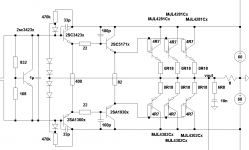
I tried this simple one in LTSpice with my current EF3 OPS:
http://www.diyaudio.com/forums/soli...imate-fidelity-amplifier-124.html#post4607602
But it's not working for me... How it should be adjusted to use it with an EF3 OPS?
I tried with 3-3 diodes and with different R values but there is still 0mA at the closed BJTs...
http://www.diyaudio.com/forums/soli...imate-fidelity-amplifier-124.html#post4607602
But it's not working for me... How it should be adjusted to use it with an EF3 OPS?
I tried with 3-3 diodes and with different R values but there is still 0mA at the closed BJTs...
Attachments
Last edited:
Oh, I see now, it's still a switching OPS just there is a smoother transition at crossover, right..?
I managed it only with 5 1n4148 with EF3 at the pre-drivers and with 47k resistor.
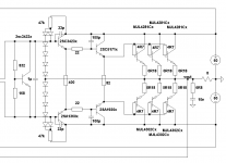
But I just saw dadod's version where it's used in the middle at the drivers:
http://www.diyaudio.com/forums/solid-state/253039-unique-cfa-120-230w-amp-5.html#post4607970
As he described if it's not optimized it can even increase distortion..?!
I managed it only with 5 1n4148 with EF3 at the pre-drivers and with 47k resistor.
But I just saw dadod's version where it's used in the middle at the drivers:
http://www.diyaudio.com/forums/solid-state/253039-unique-cfa-120-230w-amp-5.html#post4607970
As he described if it's not optimized it can even increase distortion..?!
Attachments
Oh, I see now, it's still a switching OPS just there is a smoother transition at crossover, right..?
I managed it only with 5 1n4148 with EF3 at the pre-drivers and with 47k resistor.
But I just saw dadod's version where it's used in the middle at the drivers:
http://www.diyaudio.com/forums/solid-state/253039-unique-cfa-120-230w-amp-5.html#post4607970
As he described if it's not optimized it can even increase distortion..?!
That's why in my NS-OPS I use more precise thermo-compensated voltage reference (the right Vbe spreader), that is fine-tuned in particular environment for the minimum distortion.
And how a NS-OPS should be tuned? Directly measuring it with THD/IMD?
The rough tuning method is described in my "Buildind instructions" paper here:
NS-OPS project page
It gives good enough reslt. For those, who'd like to tune with really high precision - yes, connect THD meter and tune for minimum distortion.
I tried this simple one in LTSpice with my current EF3 OPS:
http://www.diyaudio.com/forums/soli...imate-fidelity-amplifier-124.html#post4607602
But it's not working for me... How it should be adjusted to use it with an EF3 OPS?
I tried with 3-3 diodes and with different R values but there is still 0mA at the closed BJTs...
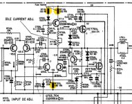
Try Technics NS OS from SU-V5 amp.
Attachments

Try Technics NS OS from SU-V5 amp.
Yes, this one will work pretty well, Clamp diodes must be fast for the best result - I used 1N5711 Schottky ones.
What's the difference to the simple one?
D309/311
C313/315
?
Why it's better to put it @ the drivers instead of pre-drivers in case of EF3 OPS?
BTW: How should I tune such a NS-OPS without distortion meter?
Just by ear..? 🙂
D309/311
C313/315
?
Why it's better to put it @ the drivers instead of pre-drivers in case of EF3 OPS?
BTW: How should I tune such a NS-OPS without distortion meter?
Just by ear..? 🙂
Try Technics NS OS from SU-V5 amp.
Standard crappy schematic for japanese amplifiers (pioneer, jvc, technics, yamaha, sony and etc.) from 80s-90s.
Standard crappy schematic for japanese amplifiers (pioneer, jvc, technics, yamaha, sony and etc.) from 80s-90s.
Well, it works, it's just not flexible enough for fine-tuning.
Clamp voltage is set by MA27A2 double-diodes, which are impossible to get these days. I use the spreader - same as the one in SU-V8 - in this case I can set the clamp limits the way I want.
Hi Valery,
How do you find the relative THD when compared to a standard switching output stage? I have simulated non switching output stages (2EF MOSFET) with connections to the drivers and direct to the MOSFET gate resistors. The results have been disappointing. While the switching noise has disappeared the overall THD increased by an order of magnitude.
Either I have been making some sort of mistake or there is a subtlety I have missed. Does this have to be implemented on a 3EF?
Paul
Hi Valery,
How do you find the relative THD when compared to a standard switching output stage? I have simulated non switching output stages (2EF MOSFET) with connections to the drivers and direct to the MOSFET gate resistors. The results have been disappointing. While the switching noise has disappeared the overall THD increased by an order of magnitude.
Either I have been making some sort of mistake or there is a subtlety I have missed. Does this have to be implemented on a 3EF?
Paul
Hi Paul,
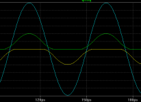
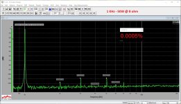
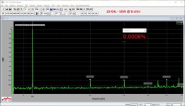
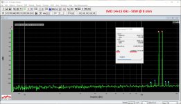
The bias clamp mechanism, I use in my NS-OPS, is arranged between the pre-driver and driver stages of 3EF follower. It reduces the overall distortion level significantly - magnitude of an order. See a rather detailed description and live measurements on my web site (the link below in my signature - both NS-OPS and VERTICAL projects). Here are just the key spectrums in combination with my Vertical front-end (attached).
Let me know if you will have questions 😉
Cheers,
Valery
Attachments

Nothing wrong with the schematic, better than 99,99% forum's designs, it's just that they didn't know at that time where sound quality was lost. Not to mention that's even more sad that still in these days folks don't have a clue. 🙂Standard crappy schematic for japanese amplifiers (pioneer, jvc, technics, yamaha, sony and etc.) from 80s-90s.
- Home
- Amplifiers
- Solid State
- Revisiting some "old" ideas from 1970's - IPS, OPS