What is the intended VAS current of the Vertical input? Will the normal sheet metal heat sink be okay, or should I use something better?
What is the intended VAS current of the Vertical input? Will the normal sheet metal heat sink be okay, or should I use something better?
As built, it runs at 8 mA, resulting in 400mW of dissipation per TO-126 transistor (+/-50V rails). I use two separate small heatsinks, they are just moderately warm.
I only had mine running for a minute, but I was running 6.8mA on each. That will likely increase as it burns in a bit. I've got the initial bias setting done on the output boards. Now I just need dig out my bench and make room for the dummy loads. No surprises so far.
Attachments
I only had mine running for a minute, but I was running 6.8mA on each. That will likely increase as it burns in a bit. I've got the initial bias setting done on the output boards. Now I just need dig out my bench and make room for the dummy loads. No surprises so far.
Looks great 😎 Yes, it burns-in during the first few minutes, so give it some time to settle.
Am I right in assuming this is going to be another cool running design? 50mA on these big Sankens hardly needs heatsink!
It seems to run nicely into a dummy load, and does run fairly cool. Heat sinks only hit 130F at full load.
One thing I did notice is the bias wanders if I move quickly near the output board. Would this be from air movement past the NTC resistor?
One thing I did notice is the bias wanders if I move quickly near the output board. Would this be from air movement past the NTC resistor?
It seems to run nicely into a dummy load, and does run fairly cool. Heat sinks only hit 130F at full load.
One thing I did notice is the bias wanders if I move quickly near the output board. Would this be from air movement past the NTC resistor?
NTC actually influences the non-switching clamp voltage, quiescent current wanders just because of the main spreader sensing. At warmed-up idle, optimal quiescent current is 50mA, it may decrease down to 40mA after running hot (high power during substantial time), then it will slowly return back to 50mA, if idle again.
Am I right in assuming this is going to be another cool running design? 50mA on these big Sankens hardly needs heatsink!
After running at 50W for half an hour, it becomes pretty warm 😉
I gave it a short audition on some test speaker. It makes a pair of crappy JBL outdoor speakers sound good! Very detailed. Next I need to cat proof it and try it out at home on some good speakers.
I gave it a short audition on some test speaker. It makes a pair of crappy JBL outdoor speakers sound good! Very detailed. Next I need to cat proof it and try it out at home on some good speakers.
My impression - combination of very controlled, elastic bass and highly natural, detailed middles and highs. Listen to some drums, cymbals - some jazz trio sort of things. Hope you will like it 😉
Hi Jeff. Nice work!I only had mine running for a minute, but I was running 6.8mA on each. That will likely increase as it burns in a bit. I've got the initial bias setting done on the output boards. Now I just need dig out my bench and make room for the dummy loads. No surprises so far.
Waiting for your listening test.🙂
I see a new protection circuit you put there.😉
I hope that heat sinks are just for test!
Regards.
Thimios
Last edited:
Hi Jeff. Nice work!
Waiting for your listening test.🙂
I see a new protection circuit you put there.😉
Regards.
Thimios
I need to finish that protection system before I can give it a proper test. It sounds great on my junk test speakers though.
I had the amp running at home for a couple hours last night. The sound is excellent, up until I noticed a tweeter or crossover starting to fail in one of my speakers. This is definitely going into a proper chassis and being added to my collection.
One observation I made is it is very susceptible to 60Hz hum with open (disconnected) inputs. More so than any other amp I've tried. It's dead silent with the input connected. Hopefully this won't be an issue in a chassis.
One observation I made is it is very susceptible to 60Hz hum with open (disconnected) inputs. More so than any other amp I've tried. It's dead silent with the input connected. Hopefully this won't be an issue in a chassis.
AmpliWire TIS - tested
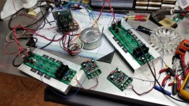
Meanwhile, I have tested my current-driven TIS (AmpliWire VFA). Terry did it earlier, I just wanted to have more detailed measurements.
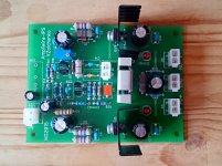
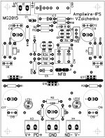
Runs nice right from the start with 6.8 mA at the output - easy to bias NS-OPS properly. Here is the schematic "as built" along with PCB layout - this one is designed by Mark (idefixes) - and a few photos.
Meanwhile, I have tested my current-driven TIS (AmpliWire VFA). Terry did it earlier, I just wanted to have more detailed measurements.
Runs nice right from the start with 6.8 mA at the output - easy to bias NS-OPS properly. Here is the schematic "as built" along with PCB layout - this one is designed by Mark (idefixes) - and a few photos.
Attachments


AmpliWire TIS - measurements
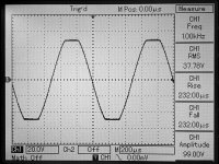
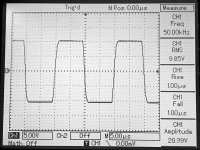
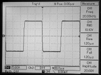
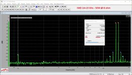
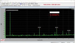
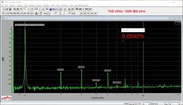
Here are the measurements in combination with NS-OPS output section.
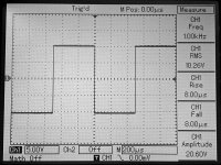
Spectrums - 50W @ 8 ohm load, square waves - 20V p-p.
Rails are +/-52V DC.
Remember - this is VFA, although it's fast enough.
THD demonstrates low dependency on the frequency, indicating the open loop bandwidth is wide enough. Good square wave response, nice symmetric clipping with no artifacts. Phase shift @ 20KHz is small enough for VFA.
No servo, however, DC offset is slowly fluctuating within +/-1mV threshold.
In overall - very cool for such a simple front-end, I would say. It's very scalable - you can build a 25W or 250W amplifier with this TIS.
Here are the measurements in combination with NS-OPS output section.
Spectrums - 50W @ 8 ohm load, square waves - 20V p-p.
Rails are +/-52V DC.
Remember - this is VFA, although it's fast enough.
THD demonstrates low dependency on the frequency, indicating the open loop bandwidth is wide enough. Good square wave response, nice symmetric clipping with no artifacts. Phase shift @ 20KHz is small enough for VFA.
No servo, however, DC offset is slowly fluctuating within +/-1mV threshold.
In overall - very cool for such a simple front-end, I would say. It's very scalable - you can build a 25W or 250W amplifier with this TIS.
Attachments
-
 DSC_0181.JPG455.5 KB · Views: 234
 -
 DSC_0180.JPG471.1 KB · Views: 255
 -
 DSC_0179.JPG468.2 KB · Views: 244
 -
 DSC_0174.JPG476.3 KB · Views: 216
 -
 DSC_0173.JPG464.4 KB · Views: 258
 -
 12-bode-1MHz.JPG102.7 KB · Views: 313
 -
 11-imd-14-15khz.JPG285.5 KB · Views: 310
 -
 10-thd-020khz.JPG267 KB · Views: 294
 -
 10-thd-010khz.JPG263.9 KB · Views: 333
 -
 10-thd-001khz.JPG279.1 KB · Views: 418
Last edited:
I only had mine running for a minute, but I was running 6.8mA on each. That will likely increase as it burns in a bit. I've got the initial bias setting done on the output boards. Now I just need dig out my bench and make room for the dummy loads. No surprises so far.
Auditioned VERTICAL + NS-OPS all day long. Runs very smoothly, moderately warm. Very clean and detailed at any volume. Extremely low noise - with my speakers it's impossible to say if it's on or off, even almost touching the speaker with your ear. Jeff, same thing with open input - a little bit of ac buzz, becoming dead quiet as soon as it's connected to the pre-amp.
Soldering the 2-nd channel, preparing to build it in a good compartment.
Attachments
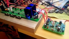
I see you have huge sinks on the drivers. Do they run hot enough to need that big?
Hi Terry,
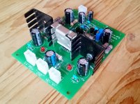
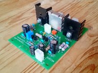
Actually, these are the "standard" heatsinks:
WAKEFIELD SOLUTIONS 637-20ABP Heat Sink, 34.9x50.8x, Square, Black Anodized, Wave-Solderable, TO-220, 9.17 °C/W, 50.8 mm, 34.9 mm
PCB is prepared exactly for them. Drivers run in pure class A, controlled by the constant current sources, so they are always pretty warm - this is one of the specialties of this design. Jeff uses the sinks with the same part number. However, simple aluminium plates will also work.
Last week, Marc (idefixes) has slightly re-designed the layout for the output devices NJW3281/1302, it also has 90 degrees drivers orientation, in one line, so that they can share the same aluminium plate - in this case, PCB length is only 220mm. So, for the future builders, this option is also available.
Cheers,
Valery
Attachments
I'm thinking of doing a layout with all outputs and drivers in a single row with the Vertical input integrated into it.
- Home
- Amplifiers
- Solid State
- Revisiting some "old" ideas from 1970's - IPS, OPS