I just looked up the ZETEX ZTX851 and it is a 5 Amp part with a lot of capacitance.
I'm not that familiar with ZETEX parts so should have looked it up earlier.
Kind of amusing that the ancient 2n4401 and PN2222A look so good.
KSC2690AY looks very good, I like it.
Right - I have also looked at Zetex datasheet. Too much capacitance.
No quasi-saturation parameters in either model.
But I am not yet that versed in the details either, so not sure if it would make much difference in your results anyway.
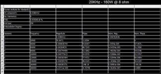
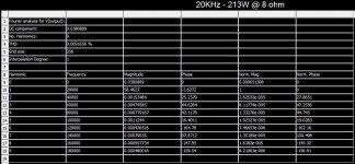
Those results show a lot of promise, what was the full power, output included 20 kHz distortion?
Best wishes
David
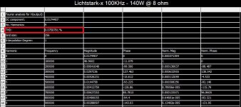
20KHz - 160W @ 8 ohm -> 0.005%
20KHz - 213W @ 8 ohm -> 0.009%
Attachments
Hi Valery,
in order to minimize DC offset, wouldn't it be preferable to return the U1/U3 bases to ground via a resistor of the same value as the NFB path resistor R22 and to inject offset correction voltage, if still any needed, into the R9/C1 connection?
Best regards!
Hi Kay,
In general - you're right, however in such double-LTP configurations, base currents pretty much compensate each other, so resistor values don't need to be matched that close.
As an option, R6 can be connected to C3 - then, 2 || 56K resistors will give the value close to the one in NFB loop.
Lichtstark-X
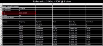
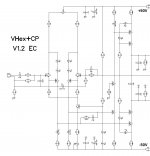
I have combined the Lichtstark front-end with very simple HexFET OPS, taken from well-tested VHex amplifier. Promising 😉
I have combined the Lichtstark front-end with very simple HexFET OPS, taken from well-tested VHex amplifier. Promising 😉
Attachments
-
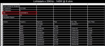 Lichtstark-x_THD_020K_140W.JPG119.8 KB · Views: 228
 -
 Lichtstark-x_THD_020K.JPG115.8 KB · Views: 189
 -
 Lichtstark-x_THD_001K_140W.JPG119.8 KB · Views: 210
 -
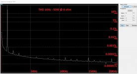
 Lichtstark-x_THD_001K.JPG119.3 KB · Views: 233
 -
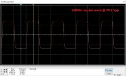 Lichtstark-x_Square_100KHz.JPG122.1 KB · Views: 295
 -
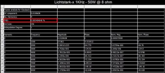
 Lichtstark-x_Spectrum_01KHz.JPG142.2 KB · Views: 293
 -
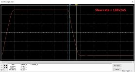 Lichtstark-x_Slew.JPG111.9 KB · Views: 562
 -
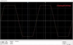 Lichtstark-x_Clipping.JPG139.3 KB · Views: 642
 -
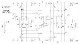 Lichtstark-X_60V_Sch.JPG160.4 KB · Views: 672
That looks like a nice addition to the VHex family.
Yep. Preparing to work on some layouts 😉

Is there a brief description of how you arrived at this Lichtstark front end?
I can wright a few paragraphs tomorrow for you.
I can wright a few paragraphs tomorrow for you.
I'm sure that you're busy and I know that you have many designs here, was there a
progression through your designs that led to this?
I think that it would be interesting but only if you have the time.
HI Valery,
if you're actually about designing a PCB layout for your Lichtstark-X power amplifier, how about increasing the front end/driver's supply voltages to, let's say +/-70Vdc (may be regulated), and how about providing three pairs of output devices, in order to increase driving capability of 4 ohms load impedance?
Best regards!
HI Valery,
if you're actually about designing a PCB layout for your Lichtstark-X power amplifier, how about increasing the front end/driver's supply voltages to, let's say +/-70Vdc (may be regulated), and how about providing three pairs of output devices, in order to increase driving capability of 4 ohms load impedance?
Best regards!
An input board for the NS output board would do this.
An input board for the NS output board would do this.
What does that mean? I'm struggling completely 😕.
Best regards!
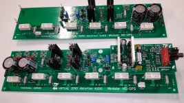
We've designed modular output boards that accept plug in input boards for our high power designs. We'll be designing an input board with this input design to plug into it.
Virtual Zero Audio - power amplifier products
Virtual Zero Audio - power amplifier products
Attachments
Current driven VAS
OK - Pete and all - here's a little bit of history behind the Lichtstark circuit 🙂
About a year ago I started thinking that driving the trans-impedance stage (VAS) with current (not with voltage) would bring a number of benefits - such as low parasitic phase shift, certain tolerance to rails ripple and other voltage-related noise components and rather good open loop linearity (if arranged properly). That's the way it evolved - going through the pictures one by one:
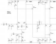
1) That's the way I came up with VHex amplifier's front-end. The VAS output circuit actually consists of two CCSs, "looking at each other". One of them (the bottom one) is controlled by the the current from Q15's collector (current subtraction). This front-end appeared to be extremely successful - simple, low-distortion, great-sounding. Note the compensation - a small lead capacitor across the NFB resistor. Well, there is also an OPS input capacitance, acting as a shunt compensation at VAS output - also rather small. That's it - the circuit is naturally stable. Later on it's been "productized" in the form of VHex+ amplifier (2 pairs of HexFETs at the output - a cool little power amp.
BTW, later on I have found out - this kind of arrangement has been used in one of the Revox commercial receivers, although my version is a bit more sophisticated 😛
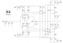
2) X4 is a symmetric front-end, explicitly designed for the higher-end line of amplifiers, based on my non-switching OPS design (NS Modular). This one is fully symmetric - it's got two equal current mirrors, driven with current from Q5, Q7 and Q8, Q3 at 4 points, subtracting currents at R14, R15 and R8, R16.
Each pair like D6, Q5 or D2, Q7 etc. is also a current mirror (asymmetric). The whole thing is very accurate, fast and low distortion. Same compensation scheme - small lead plus small shunt. This is prototyped, tested, measured, auditioned - the one I particularly like.
3) Another experiment in the same paradigm with attempt to keep the cascades operating at constant (or close to constant) power. A number of current mirrors again, the ones an the output are supplemented by the Hawksford cascode.
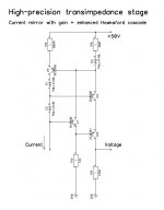
4) The idea of cascoded current mirror at the output seemed good to me, so I have designed a high-precision current mirror with gain, supplemented with my version of the Hawksford cascode (important elements are D2 and Q7). I will not go deep into the theory here, but if somebody would like analyse the currents in this arrangement - the one will see trans-impedance conversion is performed with high precision here even at very high swings.
5) Then I have designed a few relatively complicated - although very good - high-end front ends, utilizing the nested feedback (current / voltage feedback combination) - Doppelschleife and Sauberkeit. Those ones are fully commercial, I don't publish them, however, they utilize the same trans-impedance stage just mentioned above.
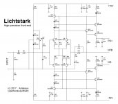
Finally I thought - why don't I drive the current mirror directly with the LTP's collector currents? That's what I did and that's the way Lichtstark was born.
The general scheme, all of the above front-ends are based on is the following:
1) Trans-conductance stage (converting input voltage into current);
2) Current scaling (likely using asymmetric current mirror);
3) Trans-impedance stage (converting the scaled-up current back to voltage).
If every cascade is the high-quality one (fast and linear) - open loop characteristics of the circuit are very good, allowing to use as much feedback as desired by the author.
Open loop THD of Lichtstark (no global NFB loop at all) < 0.003% @ 20V RMS ( < 0.008% at 44V RMS) within the whole audio bandwidth (OLG = 82db) - that's the starting point.
Hope this helps and probably inspires some better ides 😉
Cheers,
Valery
OK - Pete and all - here's a little bit of history behind the Lichtstark circuit 🙂
About a year ago I started thinking that driving the trans-impedance stage (VAS) with current (not with voltage) would bring a number of benefits - such as low parasitic phase shift, certain tolerance to rails ripple and other voltage-related noise components and rather good open loop linearity (if arranged properly). That's the way it evolved - going through the pictures one by one:
1) That's the way I came up with VHex amplifier's front-end. The VAS output circuit actually consists of two CCSs, "looking at each other". One of them (the bottom one) is controlled by the the current from Q15's collector (current subtraction). This front-end appeared to be extremely successful - simple, low-distortion, great-sounding. Note the compensation - a small lead capacitor across the NFB resistor. Well, there is also an OPS input capacitance, acting as a shunt compensation at VAS output - also rather small. That's it - the circuit is naturally stable. Later on it's been "productized" in the form of VHex+ amplifier (2 pairs of HexFETs at the output - a cool little power amp.
BTW, later on I have found out - this kind of arrangement has been used in one of the Revox commercial receivers, although my version is a bit more sophisticated 😛
2) X4 is a symmetric front-end, explicitly designed for the higher-end line of amplifiers, based on my non-switching OPS design (NS Modular). This one is fully symmetric - it's got two equal current mirrors, driven with current from Q5, Q7 and Q8, Q3 at 4 points, subtracting currents at R14, R15 and R8, R16.
Each pair like D6, Q5 or D2, Q7 etc. is also a current mirror (asymmetric). The whole thing is very accurate, fast and low distortion. Same compensation scheme - small lead plus small shunt. This is prototyped, tested, measured, auditioned - the one I particularly like.
3) Another experiment in the same paradigm with attempt to keep the cascades operating at constant (or close to constant) power. A number of current mirrors again, the ones an the output are supplemented by the Hawksford cascode.
4) The idea of cascoded current mirror at the output seemed good to me, so I have designed a high-precision current mirror with gain, supplemented with my version of the Hawksford cascode (important elements are D2 and Q7). I will not go deep into the theory here, but if somebody would like analyse the currents in this arrangement - the one will see trans-impedance conversion is performed with high precision here even at very high swings.
5) Then I have designed a few relatively complicated - although very good - high-end front ends, utilizing the nested feedback (current / voltage feedback combination) - Doppelschleife and Sauberkeit. Those ones are fully commercial, I don't publish them, however, they utilize the same trans-impedance stage just mentioned above.
Finally I thought - why don't I drive the current mirror directly with the LTP's collector currents? That's what I did and that's the way Lichtstark was born.
The general scheme, all of the above front-ends are based on is the following:
1) Trans-conductance stage (converting input voltage into current);
2) Current scaling (likely using asymmetric current mirror);
3) Trans-impedance stage (converting the scaled-up current back to voltage).
If every cascade is the high-quality one (fast and linear) - open loop characteristics of the circuit are very good, allowing to use as much feedback as desired by the author.
Open loop THD of Lichtstark (no global NFB loop at all) < 0.003% @ 20V RMS ( < 0.008% at 44V RMS) within the whole audio bandwidth (OLG = 82db) - that's the starting point.
Hope this helps and probably inspires some better ides 😉
Cheers,
Valery
Attachments
- Home
- Amplifiers
- Solid State
- Revisiting some "old" ideas from 1970's - IPS, OPS