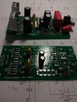
Same thing here, all difficult parts are done
Dammit, forgot the 78M15 regulators and couple of smd caps. "Waiting is the hardest part"
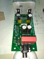
Is a heatsink needed in the IPS ? (I have the CFA version)
Hi savvas, use 7815,7915.
I have used those after the smd was fryed.
I'm on the way for the second chanel CFA IPS too.
Last edited:
Hi savvas, use 7815,7915.
I have used those after the smd was fryed.
I'm on the way for the second chanel CFA IPS too.
Thimios you are the King of IPSs.
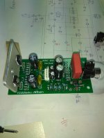
Thanks for the suggestion, I might as well use a TH regulator and get on with testing and put on a smd one later on.

You need either 15VAC x 2 Aux windings in the main transformers or run a small separate transformer for the input supply.
Up to now i use a separate toroidal for the +/-15v power supply but in one case i had strong oscillation using one big toroidal for +/-50v, one 18v+18v for the +/-15v power supply and two separate capac multiplier boards.
You need either 15VAC x 2 Aux windings in the main transformers or run a small separate transformer for the input supply.
The question is if the 15V side needs to be 15-0-15-0 or can it be 15-0-15v center tap. I'm not sure how the bridge is wired.
My small toroidal is with two separate 15v secondary windings.
I measure +19,-19v after rectifiers.
I measure +19,-19v after rectifiers.
Last edited:
That looks real nice. I have the CFA inputs built too but not tested yet because of no OPS . Hope to remedy that soon.
The 15V transformer needs to be two separate windings, center tap won't work.
That's what I thought. I only have 12.6V with two secondary outputs. Next up is 22v and I hate to waste that much voltage to a regulator. The 12.6v makes +/-17vac after rectification and +/-15v at the output. Not sure if that is enough over for the regulators to work properly.
I think the regulators usually require around 3 volts. The 22V transformer would make the regulators run pretty hot.
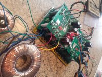
I made some standoffs and stacked them. I mounted them on a plate to serve as heatsink and a way to mount the whole thing in a case. It takes up a lot of real estate. Testing it with the 12.6vac transformer and 34vac transformer. Getting 15v on the low side and +/-52V on the high side. I'll probably go to a 39-0-39vac transformer once I have everything set up.
Blessings, Terry
Blessings, Terry
Attachments
Last edited:
can anyone describe me about the sound from the NSOPS? I find the highs to be nice and clear as well as mids being good as well but the bass is something what am I missing did anyone feel the same? I initially thought its too tight bass or so but I found that the excursion of the LF itself isn't happening much. I read it somewhere in the thread that NS bass is kind of laid back. Correct me if im wrong here or anyone found a better way to fix it? im using red 1.8V LED for the class A driver stage biasing. I tried with blue but the bias is sticking up at about 0.3Amp
can anyone describe me about the sound from the NSOPS? I find the highs to be nice and clear as well as mids being good as well but the bass is something what am I missing did anyone feel the same? I initially thought its too tight bass or so but I found that the excursion of the LF itself isn't happening much. I read it somewhere in the thread that NS bass is kind of laid back. Correct me if im wrong here or anyone found a better way to fix it? im using red 1.8V LED for the class A driver stage biasing. I tried with blue but the bias is sticking up at about 0.3Amp
After all, it's just a powerful EF3 with bias clamping (that you can turn off if you like). The original design uses blue LEDs (3.2V). The red ones (1.8V) can also be used, but they require the CCS emitter resistors of the lower value for keeping the driver stage idle current high enough.
Optimal quiescent current of the output transistors is 62.5mA per pair.
"I read it somewhere in the thread that NS bass is kind of laid back." - that was most likely related to the combination with Vertical CFA front-end, but that's the specialty of that particular front-end.
Combination with Tubsumo front-end gives very deep, rich bass.
OPS has got no issues with bass. It's just not possible by design.
Something is wrong with the build.
Cheers,
Valery
Hi Valery thank you very much for the reply. What I tried is with +/-60V rails and with LED which has forward bias of 1.8V. I think ill change it to 3.2 or more to get better idle current. As there are 3 pairs in OPS the idle current of each transistor is about 30ma so for pnp and npn pair its 60ma across. How much Idle current is ideal for the driver stage? I guess since its a class A driver stage it doesnt let the drivers to shut down when the current demand is more?
Now coming to the math of the driver stage idle current does it needs to be more than the max consumption of output stage driver current? as per the simulation found that each transistor consumes 15ma max so 60ma to be the driver stage idle current?
Now coming to the math of the driver stage idle current does it needs to be more than the max consumption of output stage driver current? as per the simulation found that each transistor consumes 15ma max so 60ma to be the driver stage idle current?
Last edited:
The right value of idle current for the driver stage is around 18mA.
At high swing, the peak current values go significantly higher, but during the "off" half-wave, it comes back to idle (18mA), never going lower than that.
The idle current of the output pairs - each pair (npn + pnp) has got the same current value at idle, as they work in series. The idle current goes from the positive rail, through npn, through pnp, to the negative rail. 62.5 mA (after initial warm-up) is the value providing the lowest distortion.
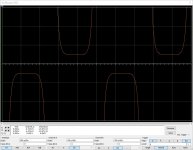
In addition to that, the clamping spreader has to be tuned-up for the lowest distortion, preventing the output transistors from closing. The attached picture shows the crossover region of the current through the output transistors - emitter current comes close to zero but never reaches it.
However, even if the idle current clamping system is not tuned up the best way, it doesn't influence the bass performance. The OPS works correctly even with DC signals - there's no cut-off frequency at the low end of the bandwidth.
At high swing, the peak current values go significantly higher, but during the "off" half-wave, it comes back to idle (18mA), never going lower than that.
The idle current of the output pairs - each pair (npn + pnp) has got the same current value at idle, as they work in series. The idle current goes from the positive rail, through npn, through pnp, to the negative rail. 62.5 mA (after initial warm-up) is the value providing the lowest distortion.
In addition to that, the clamping spreader has to be tuned-up for the lowest distortion, preventing the output transistors from closing. The attached picture shows the crossover region of the current through the output transistors - emitter current comes close to zero but never reaches it.
However, even if the idle current clamping system is not tuned up the best way, it doesn't influence the bass performance. The OPS works correctly even with DC signals - there's no cut-off frequency at the low end of the bandwidth.
Attachments
- Home
- Amplifiers
- Solid State
- Revisiting some "old" ideas from 1970's - IPS, OPS