Thimios,
Thanks, i did not know this boards... i appreciate this.
For now i will love to be able to fix this all school circuit, i did the same measurement that you and when i removed one of 35 Vac wire i have 20,7 Vac the same measurement when the two 35 Vac wire are connected
It works the right way only if those AC signals, coming to D7, D8 are 180 degrees in phase. The same phase will not work 😉
Exactly!It works the right way only if those AC signals, coming to D7, D8 are 180 degrees in phase. The same phase will not work 😉
It works the right way only if those AC signals, coming to D7, D8 are 180 degrees in phase. The same phase will not work 😉
And how to do to be at 180 degrees and to use two different phase?
You need to use the right (opposite) sides of the transformer windings. AC signal phase on two sides of the winding is opposite (180 degrees). You need to connect one side of the first winding to D7 and the opposite side of the second winding to D8.
Hi Hicoco,
leave the recification circuit as it was, and connect the ac points of the rectifier to your protection circuit, then it should work.
Günni
leave the recification circuit as it was, and connect the ac points of the rectifier to your protection circuit, then it should work.
Günni
Last edited:
And how to do to be at 180 degrees and to use two different phase?
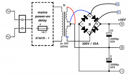
Look at the Elektor wiring diagram.
Connect one wire from rectifier A. C to D7.
Connect another wire from the 2nd rectifier A. C to D8.
Connect another wire from transformer's center tap to 0 on the protection board.
Make all other connections like, from the speaker out, current sence, power supply, gnd.
There are 3 connection points for gnd on the protection board.
Last edited:
Hi Hicoco,
you must invert the upper windings of the transformer. As you connect on your attachment, the two windings are connected inparallel and both windings are in phase.
BR
you must invert the upper windings of the transformer. As you connect on your attachment, the two windings are connected inparallel and both windings are in phase.
BR
Hicoco, your post #2800 pazle me.
Are you sure that you measure 20v at the point where cathodes D7. D8 connected and the same time 1.1v across led?
Are you sure that right value resistors used for R30 R31?
Are you sure that you measure 20v at the point where cathodes D7. D8 connected and the same time 1.1v across led?
Are you sure that right value resistors used for R30 R31?
Last edited:
Hicoco, your post #2800 pazle me.
Are you sure that you measure 20v at the point where cathodes D7. D8 connected and the same time 1.1v across led?
Are you sure that right value resistors used for R30 R31?
Thimios no you are right i was with 4,7K value for both.
i had put back the right value 10k and now i have:
When i have the two 35V (real 37,5V) wire connected
35v after D7.D8
1,097V after R30
97mv at T10 base
When i have one 35V (real 37,5V) wire disconnected:
22,2V after D7. D8
1,061 after R30
227mV at the base of T10
That work perfectly now the relay are deenergized instantaneity when i disconnect one 35V
Thank again Thimios for your help,
i really appreciate
FR

Last edited:
Good to hear, that it works now.
Now i can continue , building up and test my on LSP_Servo PCBs based on the Crescendo Millenium circuit.
BR Günni
Now i can continue , building up and test my on LSP_Servo PCBs based on the Crescendo Millenium circuit.
BR Günni
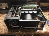
Tribute 3000
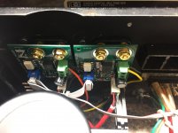
I have the Amp control and DC detection boards installed in chassis for the Tribute 3000. On the Tribute 3000 OPS there is a 2 wire pin labeled OFFSET. Should these be connected to anything?
When I turn on the amp the relays click and after about 5 seconds click again and I get a rapidly blinking LED, DC offset alarm I believe.
Bias and DC Offset were set before I installed the amp control boards and Jeff had adjusted and tested those. So I'm thinking it must be a wiring mistake.

- Home
- Amplifiers
- Solid State
- Revisiting some "old" ideas from 1970's - IPS, OPS