Again searching for '211,' but this time at your second link:...they used a 211 kHz sample rate, but apparently that's for the DAC2...
"It is important to note that the DAC2 and DAC3 converters frequency-shift the selected built-in filter by driving the converter chip at a fixed 211 kHz sample rate."
True, but ASRC and USB transfer mode both have to do with jitter suppression in dacs....resampling has nothing to do with the USB transfer mode...
All the links to ancient (by IT timeframe) articles are pointless. Especially anything written before UAC2 was in widespread use is mostly outdated.
The benefit of async UAC over sync/adaptive UAC is quite clear. Most (if not all) async USB-I2S boards use a FIFO sample buffer. This buffer can eliminate the jitter related to USB transfer or host. So the only source of jitter comes from generating the I2S signals. Adaptive/sync UAC has USB/host jitter from adapting to host data rates but also the additional jitter from generating the I2S signals.
EDIT: While it is possible to use FIFO buffers also with sync/adaptive UAC avoiding buffer overruns/underruns will be challenging as data rate is controlled by the host.
Last edited:
Yes to all. Also, IMO the better DAC chips use external master clock for the conversion and do not generate the conversion clock from the incoming I2S signal. So IMO the most logical and clean way is to use the DAC master clock for USB async feedback and consume I2S as is generated by the USB receiver chip. The chip already has a short FIFO at its I2S output, clocked-out by the DAC master clock, appropriately divided to fit the bitrate.
Asynchronous USB board can of course use the same clock as DAC. Clock used for generating I2S is not the same as USB clock.
Latency depends on the buffer size. My STM32F723 board uses 4k sample buffers per channel regardless of sample rate (44k1 to 768k).
Latency depends on the buffer size. My STM32F723 board uses 4k sample buffers per channel regardless of sample rate (44k1 to 768k).
A general-purpose audio DAC normally has to work with S/PDIF, AES3 or Toslink inputs, which means it has to be able to work with an input sample rate that is derived from the source's clock. Either it has to lock its own clock to whatever comes in, or to use asynchronous sample rate conversion.
If you listen to a live stream via a computer for a long time, you also need something somewhere to correct for clock frequency differences between the computer that broadcasts the live stream and your local clocks.
If you listen to a live stream via a computer for a long time, you also need something somewhere to correct for clock frequency differences between the computer that broadcasts the live stream and your local clocks.
The size of the input buffer of the USB receiver may be a factor. And why Gordon Rankin and others chose the old (2001) Texas Instruments TAS1020 USB device. It's even older than the CM108 (2003). Rankin supposedly wrote his own async software that was stored in a separate EPROM chip, and that was somehow interfaced with the TAS1020.
AudioQuest Dragonfly and other popular, commercial USB dacs also use this device.
But if jitter performance is what you're after, there are other ways to get that than the async vs sync USB debate.
EDIT: In the Stereophile Wavelength Cosecant review (2009), JA noted simply switching to a battery-powered computer can improve jitter of the asynch USB dac.
https://www.stereophile.com/content/wavelength-cosecant-v3-usb-digitalanalog-converter-measurements
Finally, at first I didn't measure as good jitter rejection from the Cosecant as I had expected to from the graphs that Wavelength's Gordon Rankin had sent me, and from the fact that it operates in asynchronous USB mode with the DAC controlling the flow of data from the host computer. Using the AC-powered Mac mini as the source of the 16-bit Miller-Dunn J-Test signal, while data-related sidebands were absent from the FFT-derived, high-resolution spectrum of the Cosecant's output, some sidebands were present at AC power-supply–related frequencies and there was some spectral spreading of the central spike that suggested the presence of random low-frequency jitter (fig.12). I retested the Cosecant using the battery-powered MacBook. Again, no data-related sidebands can be seen (fig.13), and now the central spike is well-defined, with just one pair of sidebands visible ±60Hz. This is the best jitter performance I have measured from a DAC fed USB audio data.
Last edited:
Buffer size of async UAC device has little to do with jitter. Of course it is possible that battery-powered asynch UAC board may have lower jitter than AC/USB-powered but regardless of how it is powered it will still be miles ahead of sync UAC. And TAS1020 may have been good USB controller for UAC1 before UAC2 came along. Absolutely no reason to use it today.
Anyone know what the "Group Delay" feature may be?
Found on most ASRC chips.
It's Pin 1 on both SRC4192 and AD1896.
TI calls it "Low group delay control input (active high)".
Both datasheets mention this pin's effect on digital filtering.
Found on most ASRC chips.
It's Pin 1 on both SRC4192 and AD1896.
TI calls it "Low group delay control input (active high)".
Both datasheets mention this pin's effect on digital filtering.
Not sure about specific applications.Digital filtering options allow for lower group-delay processing. These include a low
group-delay option for the interpolation and resampler function, ...
AFAIK the more recent Dragonfly uses a PIC. Not old so it can't be any good 😀 Never understood the hype as dongles are a plain nuisance. They are also more expensive than a full fledged DAC and have less features/inputs.The size of the input buffer of the USB receiver may be a factor. And why Gordon Rankin and others chose the old (2001) Texas Instruments TAS1020 USB device. It's even older than the CM108 (2003). Rankin supposedly wrote his own async software that was stored in a separate EPROM chip, and that was somehow interfaced with the TAS1020.
AudioQuest Dragonfly and other popular, commercial USB dacs also use this device.
Is the plan to use the oldest ASRC chip to drive old DAC chips?
Last edited:
Actually, I use a low-$ dongle DAC with my Win 7 Dell laptop daily. It's this one: https://hifimediy.com/product/s2-dac/AFAIK the more recent Dragonfly uses a PIC and some have a SA9023. Never understood the hype as dongles are a plain nuisance. They are also more expensive than a full fledged DAC
ESS Sabre ES9038Q2M DAC chip and SABRE9602 output stage driver. SA9023 USB receiver chip
I improved it a bit with a cheap Amazon USB isolator.
There is no romance in that, marantzphilips.
BTW I promised to look for old Sony DAC ICs but I forgot. I did find old 5V low jitter clocks for Sony yesterday.
BTW I promised to look for old Sony DAC ICs but I forgot. I did find old 5V low jitter clocks for Sony yesterday.

Anyone know what the "Group Delay" feature may be?
Found on most ASRC chips.
It's Pin 1 on both SRC4192 and AD1896.
TI calls it "Low group delay control input (active high)".
Both datasheets mention this pin's effect on digital filtering.
Not sure about specific applications.
You can usually choose between different FIFO lengths (page 17, right column AD1896 datasheet). The longer the FIFO memory, the more irregular the input sample rate can be without the ASRC having to switch to a wider tracking loop bandwidth to ensure that the FIFO doesn't become empty or completely full, but the more the signal gets delayed. Too much delay can be a nuisance for sound reinforcement and video applications.
Maybe you can find a BBC AESIC to go with the rest of the dinosaurs.Is the plan to use the oldest ASRC chip to drive old DAC chips?
The "default" (0) is long. Short is (1). I think I want short because a modern USB Amanero device -- what I'm feeding the ASRC with at the moment -- is likely spitting out some pretty clean (jitter-"free") I2S. Yes?You can usually choose between different FIFO lengths (page 17, right column AD1896 datasheet). The longer the FIFO memory, the more irregular the input sample rate can be without the ASRC having to switch to a wider tracking loop bandwidth to ensure that the FIFO doesn't become empty or completely full, but the more the signal gets delayed.
I think it won't matter much when you only use it for music playback with a clean source; who cares whether the music starts 1.1 ms later?
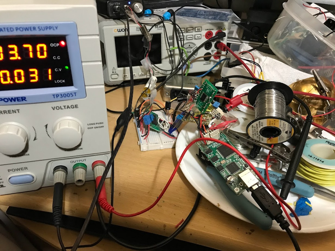
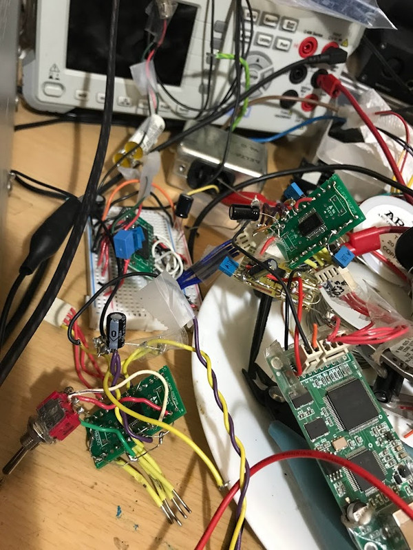
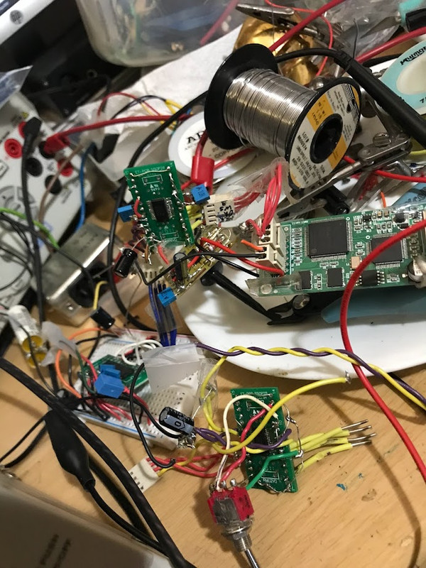
Some experiments with an SRC4192 asrc. To quote Han Solo, "Sorry about the mess."
Anyway ...because the SRC4192 and AD1896 are pin compatible, it was easy to "plug-n-chug".
Weird things happen when one precedes the TDA1305T with such devices. For one, using that variable Tekpower PSU, you can play with voltage and see what happens.
With the AD1896, the max usable voltage for the TDA1305's Vcc pins (before sound distorts, and cuts out at 4.7v) is 4.4vdc. The min. TDA1305's Vcc pin is about 2.3v (yes, it will continue to work well below its datasheet min of 3.4v!!) . That max voltage is strange for the 1305 because its nominal is 5.0.
The SRC4192 is much more fussy. Upon initial installation into that "mess", I almost though something was defective or mis-wired. No ... simply reducing TDA1305 Vcc from 4.4 to 2.8v got music playing. Looking at the 4192's DS, the block diag. does specify the use of decoupling caps on the analog and digital Vcc pins. Adding those (and adding some more 100nF to the 1305 Vcc pins) allowed me stabilize the mess and use up to 4.2 V on the 1305.
Even with all that extra tweaking of the SRC4192, the AD1896 (w/o tweaks) sounds much better and cleaner. Who knows ... with another DAC following these ASRCs, results may be completely reversed. Lots of possibilities in the parts bin ... AD1853 and 1955. Maybe, TI1792 or 1794. Or even CS4398.
What IO supply voltage do you use for the AD1896? The DAC is only guaranteed to work when the high input level is at least 70 % of its digital supply, 80 % for the clock input. Besides, the long unterminated wires and poor or nonexistent supply decoupling won't help.
- Home
- Source & Line
- Digital Line Level
- Revisiting ASRC (sample rate conversion) and up-sampling