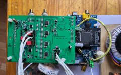
My suspicion would be the soldering of U7, U9, U14, U16. They are not easy to spot when there are bridges between pins. Having assembled a few of these boards I have had bridges and/or dry joints on at least two boards on these devices. I would reflow/solder wick them.
As Marcel indicated, you can measure DC on the four outputs with DSD signal on and check for 1.24v on each outps and outms, left and right . This is a quick and easy test and will reveal at least which device to concentrate on if you do not see 1.24v.
As Marcel indicated, you can measure DC on the four outputs with DSD signal on and check for 1.24v on each outps and outms, left and right . This is a quick and easy test and will reveal at least which device to concentrate on if you do not see 1.24v.
I will use a high impedance headphone to tap each point in the path to start with, since DSD is audio signal.
Floored by the help here, you guys.. lets chew first bite of help here from Marcel..my god I can't believe
Begs mercy😅
Begs mercy😅
1:10 probe or 1:1 probe?
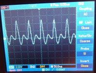
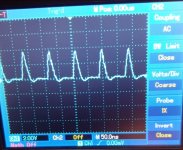
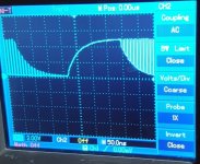
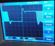
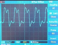
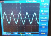
I guess the first plot (with the ringing) is on the side of the driving EXOR gate. They both look quite reasonable, considering the effect of the probe.
Were you playing DSD128? If so, the frequency is about right.
I guess the first plot (with the ringing) is on the side of the driving EXOR gate. They both look quite reasonable, considering the effect of the probe.
Were you playing DSD128? If so, the frequency is about right.
Probe was1:1, lets fix to 1:10 now.1:10 probe or 1:1 probe?
I guess the first plot (with the ringing) is on the side of the driving EXOR gate. They both look quite reasonable, considering the effect of the probe.
Were you playing DSD128? If so, the frequency is about right.
My receiver toslink only gets 48khz PCM.
From that on, I don't know what DSD outputs the PCM2DSD module.
My receiver toslink only gets 48khz PCM.
From that on, I don't know what DSD outputs the PCM2DSD module.
Could you check the clock that goes into the DAC? What frequency does it have?
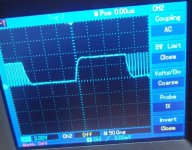
The latest FPGA configuration of PJotr25 and olo111 is supposed to run at a DSD256 rate, so the bit clock frequency should be around 11 MHz or 12 MHz before doubling. You get that after doubling, which is very strange. Except for the too low frequency, the doubled clock looks normal.
How do you drive the PCM2DSD from a Toslink interface? Could you give some details about what is connected to what?
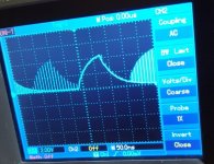
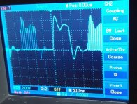
I got very confused by the data waveforms, but I guess the narrow peaks are some sort of hatching feature of your oscilloscope: when a signal is in some runs low and in others high, it apparently hatches. I've never seen anything like that before.
Last edited:
The R129 waveforms show return-to-zero behaviour, as they should, but the R131 waveforms don't. They look just like the data input signal at R126, except for level shifting and the effect of the probe.
Pic atch is the receiver module, I use his optical toslink input.
The output IIS interface matches the pinout exactly to plug the PCM2DSD module (Amanero input). It is PCB version 1.0 2020.
Output signal right& left comes from pin 3 DATA and pin 5 FSCLK straight to the so called NoDac filter, a 3rd order Butterworth -good spell? and then a stepup transformer. Turned to sound good enough, detailed and dinamic. It is for three month listening.
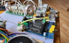

Pic atch is the receiver module, I use his optical toslink input.
The output IIS interface matches the pinout exactly to plug the PCM2DSD module (Amanero input). It is PCB version 1.0 2020.
Output signal right& left comes from pin 3 DATA and pin 5 FSCLK straight to the so called NoDac filter, a 3rd order Butterworth -good spell? and then a stepup transformer. Turned to sound good enough, detailed and dinamic. It is for three month listening.
View attachment 1447728
What's the brand and type of the lower board, the one with the Toslink interface? I see A2250 on it, but typing in A2250 at duckduckgo.com only leads to information about a treadmill meant as exercise equipment.
Last edited:
The receiver comes from Aliexpress, in the description I read 'B37 digital board', hope link works:
69,87€ | 1.3 inch OLED AK4137 SRC Digital Audio Processing BNC RCA Fiber Coaxial Input 384K DSD256 Supports DSD PCM DOP Remote Control
https://a.aliexpress.com/_EI0coYy
69,87€ | 1.3 inch OLED AK4137 SRC Digital Audio Processing BNC RCA Fiber Coaxial Input 384K DSD256 Supports DSD PCM DOP Remote Control
https://a.aliexpress.com/_EI0coYy
Last edited:
OK, you have a Toslink receiver board with asynchronous sample rate converter.
What frequency do you see at R3 of the DAC board? Twenty-something megahertz or about half of that?
What frequency do you see at R3 of the DAC board? Twenty-something megahertz or about half of that?
- Home
- Source & Line
- Digital Line Level
- Return-to-zero shift register FIRDAC
