I have taken the same stance on any claims based on sighted subjective listening tests. No matter who makes the claim.Hence I recommend to regard the ABX tests, according to the method promoted by the ABX company in Troy, Michigan, as an utter waste of time, as their failure to reject the null hypothesis has neither statistical significance nor power.
I see too many 'You's in the last couple of posts.
Play the ball and not each other.
Hugo
Play the ball and not each other.
Hugo

Just to clarify, as this test was about PCM2DSD with Marcel's RTZ dac recording PCM2DSD output does not provide valid information. Recording dac output is necessary to have comparable recordings of the whole.If you want to do fair tests you need to loopback the digital output of PCM2DSD and record it into a DSD file. Then use high quality professional software such as Pyramix to convert to PCM.
That sounds logical. The low-level distortion issues, for example, are an interaction between the modulator, that generates far-ultrasonic tones, and the DAC, that processes those ultrasonic tones and generates (very low level) intermodulation products at audio frequencies.
Marcel, Does it not matter if the ADC linearly distorts the signal coming out of the dac? Transients can be mis-aligned thus make the more dynamic FPGA sound more compressed than is the reality coming out of the dac. All you know about the ADC is noise and magnitude spectra look okay in the absence of strong RF at the input; you don't have a measurement of what it does to phase in the audio band? The result a measurement also depends whatever the output stage in use is doing to signals. Maybe such as process is useful for chasing around spurs, but its very hard to see what use it would have that humans should be subjected to.
Most recordings (if not all) go through ADCs. Most of ADCs that have been used in recordings are quite likely not better than what was used in this test. So many transients may have been mis-aligned already. Some new transients may have been added by e.g. the FPGA.
I don't think there is any way to compare DAC output signals digitally without using an ADC.
What you could do when you just want to compare how two digital sigma-delta modulators would work with an imperfect DAC is to make a digital model of an imperfect DAC and pass the digital signal through it. That's what I did very coarsely when in some simulations, I changed the bit weight by +/- 1 ppm depending on the previous bit.
What you could do when you just want to compare how two digital sigma-delta modulators would work with an imperfect DAC is to make a digital model of an imperfect DAC and pass the digital signal through it. That's what I did very coarsely when in some simulations, I changed the bit weight by +/- 1 ppm depending on the previous bit.
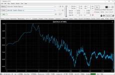
What may have gone unnoticed amidst all the noise is that the "null" reached in these recordings is remarkably good. That may be mostly due to the ADC and synchronization but no doubt Marcel's dac has something to do with it as well.
At ASR some member made a similar synchronized recording with Mola Mola Tambaqui and RME ADI-2 Pro as ADC. The DeltaWave "null" was quite different from what was reached here. Maybe the PLL clock in ADI-2 has something to do with it.
At ASR some member made a similar synchronized recording with Mola Mola Tambaqui and RME ADI-2 Pro as ADC. The DeltaWave "null" was quite different from what was reached here. Maybe the PLL clock in ADI-2 has something to do with it.
Attachments
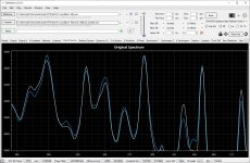
No question that a calculation can be done to match average EQ Magnitude over a fixed time period -- using FFT techniques bin by bin, of course.
But to what practical end? A calculation can be done to show the average shape and color of an orange and an apple has properties like neither the apple nor the orange did in the first place. So what?
EDIT: Marcel, do you believe merely adjusting gain and time offset in the time domain can perfectly match FFTs of two signals in the frequency domain that have clear and obvious different frequency distributions to begin with? Just checking to see if anyone around here would like to take a stab and explaining the math?
Last edited:
Who has suggested that?No question that a calculation can be done to match average EQ Magnitude over a fixed time period -- using FFT techniques bin by bin, of course.
There are members here who have quite a bit of experience on DeltaWave. Why don't you ask them?EDIT: Marcel, do you believe adjusting gain and time offset in the time domain can match FFTs of in the frequency domain that have different frequency distributions to begin with? Just checking to see if anyone around here would like to take a stab and explaining the math?
https://www.audiosciencereview.com/...ompletely-pointless-or-not.27058/post-1957682
We don't know what DeltaWave does. What we may know is what some people think it does, but so far that seems mathematically implausible.
There is a thread on ASR. That is the best place to get answers as the developer is very helpful.
https://www.audiosciencereview.com/...test-deltawave-null-comparison-software.6633/
https://www.audiosciencereview.com/...test-deltawave-null-comparison-software.6633/
Not true. As I've said before if the matching of the waveforms in time domain is good the resulting frequency domain spectras will be well matched as well.so far that seems mathematically implausible.
EDIT: Marcel, do you believe merely adjusting gain and time offset in the time domain can perfectly match FFTs of two signals in the frequency domain that have clear and obvious different frequency distributions to begin with? Just checking to see if anyone around here would like to take a stab and explaining the math?
Adjusting gain should only cause a vertical shift in a DFT plot that only shows the magnitude and does so on a decibel scale.
Adjusting offset will only affect the zero frequency bin and depending on windowing, some just above zero frequency.
Time shifting could drastically change the DFT plot if it changes the part of the non-steady-state waveform that is used for calculating the DFT. That's my latest guess, it would be nice if someone could confirm or deny it.
They were both supposed to be for 10s, starting at 10s from the beginning then ending at 20s into it. Its that not how it works, given there is no manual?
Besides it matched them perfectly, so the full 5min recording must sound perfectly like only the first 60s of it?
Besides it matched them perfectly, so the full 5min recording must sound perfectly like only the first 60s of it?
What may have gone unnoticed amidst all the noise is that the "null" reached in these recordings is remarkably good. That may be mostly due to the ADC and synchronization but no doubt Marcel's dac has something to do with it as well.
At ASR some member made a similar synchronized recording with Mola Mola Tambaqui and RME ADI-2 Pro as ADC. The DeltaWave "null" was quite different from what was reached here. Maybe the PLL clock in ADI-2 has something to do with it.
In my experience, how good of a null you can achieve is almost solely based on frequency response (magnitude and phase). Things like DC high pass behavior, frequency response ripples and non-linear phase filter response have a huge impact on the results. It is easy to a see a 40 dB improvement in the null by implementing a FIR filter to correct these frequency response deviations.
I agree that a -69 dB rms null is quite good.
Michael
- Home
- Source & Line
- Digital Line Level
- Return-to-zero shift register FIRDAC