I need a doubled BCLK, don't I?
Guess I could reclock the XOR doubled clock. Except its already at 22/24MHz for DSD256. I don't want to use 45/49MHz for MCLK because close-in phase noise gets to be too much.
That said, I would consider using 45/49MHz clocks if I have to for higher end consumer market equipment. For the really high end part of the dac market, I don't think I would go that high with MCLK. One can hear the difference if the rest of the system is good enough, at least IME that's can be the case.
Last edited:
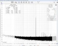
I actually tested this with my setup. So USB-I2S+PCM2DSD using 22M/24M NZ2520SDA's. This is quite easy to setup on my RTZ board as I have onboard bit clock reclocking from the same MCK. I just used the same MCK for doubled bit clock.Regarding crystal clocking of RTZ versus the XOR clock doubler
Even with my quick&dirty mod this resulted in measured improvement in the -60dBFS issue (see below).The tallest peaks were about 5-10dB lower than earlier. At higher levels measured improvement was less. Also I noticed the improvement with only 44k1/88k2 fs but not with 48k/96k fs.
Attachments
Nice filter calculator where component value series can be chosen...
Load tool: https://markimicrowave.com/technical-resources/tools/lc-filter-design-tool/
//
Load tool: https://markimicrowave.com/technical-resources/tools/lc-filter-design-tool/
//
I actually tested this with my setup. So USB-I2S+PCM2DSD using 22M/24M NZ2520SDA's. This is quite easy to setup on my RTZ board as I have onboard bit clock reclocking from the same MCK. I just used the same MCK for doubled bit clock.
Even with my quick&dirty mod this resulted in measured improvement in the -60dBFS issue (see below).The tallest peaks were about 5-10dB lower than earlier. At higher levels measured improvement was less. Also I noticed the improvement with only 44k1/88k2 fs but not with 48k/96k fs.
That's quite interesting. You previously saw a clear dependence of the low-level distortion on the output filter, now on the way you generate the shift register clock, even though you have the correct frequency in both cases you compare.
That could mean that there is a filter-related part and a data-to-clock crosstalk related part.
It could also mean that the suppression around fs/2 of the FIRDAC is somehow affected by the clock generation method. With less suppression, the output filter has to handle larger spurs and produces more intermodulation.
If you have the equipment to measure it, do you see any difference in the levels of the FM-like tones between 5.6348 MHz and 5.6548 MHz at the 8.2 nF between the two clocking methods?
I was not aiming for 80kHz fc. My first filter had fc at about 53kHz. The second one at 65kHz.
I would suggest to shoot for a much higher turnover for the LC.
If our BCK is appx. 12MHz the range from 6MHz to 12MHz must be suppressed preferably by > 120dB.
Depending on modulator we should have 80kHz noise free bandwidth at DSD256 for a 7th order modulator.
From 60kHz to 6MHz is two decades.
Let's keep our 2nd order MFB LPF at (say) 60kHz. Past 1MHz or so we cannot really trust this filter, but say from 60k to 600k a MFB filter will do fine.
So we want the LC filter to cut in somewhere above 60kHz and below 1MHz. We also want a steep slope, with CLCLC we get 5th order for HF. That is 100dB per decade.
So a 600kHz turnover for the LCLC part tied in with the MFB filter so that it leaves the sub-100kHz response alone and minimally affects the "virtual ground" impedance will kill together with the input cap set for our (say) 60kHz MFB all the HF noise we want it to.
This filter needs much less inductance, a starting point for a sim might be Marcel's original MFB LPF, with 22u/10n/22u/3.3n inserted between the cap at DAC (8.2n) and the I/U converter.
The MFB filter will need retuning, but it should be possible to not insert more than a few 100mOhm between DAC and virtual ground while improving the rejection of noise from the DS DAC where it matters by something like 80dB.
Thor
Last edited:
Yes. Then I read it right. The P-Channel source connects to Vcc (say 5V). The switching voltage of the pair is at ~1.5V, where it draws maximum current.
That means the TH voltage (e.g. Id > 100uA) of the N-Channel is a little higher, say 1.7V from Vss and the TH Voltage of the P-Channel is a little lower, referenced to Vss perhaps 1.3V.
But the P-Channel transistor must reference Vcc, so it's TH voltage would need to be 3.7V.
I don't know what you see in the graph:
but looking at the upper (SN74AHC) graph, I see that current flows from about 0.7 V to 4 V. Assuming a 5 V supply, that is consistent with a 0.7 V NMOS threshold voltage and a -1 V PMOS threshold voltage. The lower (SN74AHCT) graph stops conducting current around 3 V, consistent with a stack of two PMOS transistors with -1 V threshold voltage. I also see that the graphs don't look very quadratic and that the moderate and weak inversion regions aren't visible.
Anyway, the overlap current for SN74AHCT at 3.3 V is smaller than I expected, so that's nice.
So far all low-level distortion measurements I know of were done with bohrok2610's layout, as far as I remember. Has anyone done similar measurements with the original layout or any other layout variant and if so, what were the results?
@MarcelvdG :
No, I have not. When I observed that the versions I had made did not perform to the same level as bohrok2610s I focused on trying to find out what caused the lower performance. So unfortunately no feedback on this ...
Jesper
Has anyone done similar measurements with the original layout or any other layout variant and if so, what were the results?
No, I have not. When I observed that the versions I had made did not perform to the same level as bohrok2610s I focused on trying to find out what caused the lower performance. So unfortunately no feedback on this ...
Jesper
I only have a 200MHz scope but that does not help.If you have the equipment to measure it, do you see any difference in the levels of the FM-like tones between 5.6348 MHz and 5.6548 MHz at the 8.2 nF between the two clocking methods?
One thing worth mentioning is that I used MCK only for shift registers. Using MCK also for last serial data flipflops increased noise floor by about 20dB. I assume this is due to setup/hold time issue with flipflops. So probably no sense in testing crystal clocking with current RTZ circuit.
@PJotr25 measured this with the original DAC layout. There doesn't seem to be much difference.
To be more precise, the "big" peaks that behave according to the FM modulator theory are similar (though not exactly the same), but the small peaks that shift far less with offset than they should according to the FM modulator theory are nowhere to be found.
bohrok2610's measurement, -60 dB, 1 kHz, old PCM2DSD configuration, 96 kHz PCM sample rate, bohrok2610's DAC PCB, zoom around 3 kHz:
PJotr25's measurement, -60 dB, 1 kHz, old PCM2DSD configuration, 48 kHz PCM sample rate, original DAC PCBs, zoom around 3 kHz:
No idea what to conclude from this.
IIRC Bohrok2610 does not use X5R bypass caps for the shift registers, among the other various differences mentioned?
Anyway, seems to me there are maybe three of four various areas of focus to consider which have been mentioned so far:
1. Output stage distortion and or mushy sound
2. Possible Vref effects
3. RTZ generation
4. Shift register bypass layout
Area there any others I missed or that should be added to the list?
If not, my personal responses to the list would be as follows:
1. Go ahead and try the OPA1632 output stage, with or without transformer isolation
2. IME its hard to beat a simple, maybe 3-4 transistor shunt physically close to the dac D/A conversion
3. IME Clocked is going to be more precise sounding
4. IME Ground fill under the shift registers will turn out to work better than ducking bypass through vias
IOW, some of this stiff has been seen by other people already and some results have been obtained. Unfortunately however, no measurements to share.
Also its not like all the circuitry is in an IC, so indirect methods don't have to be used to investigate; this circuitry can be modified and probed fairly easily, all without the cost of a new mask.
Moreover, we should try to avoid any unnecessary "analysis paralysis."
As an aside, the above comments are offered in he spirit of getting the best out of the dac even if it costs substantially more to make. Maybe one goal of the project as Marcel has envisioned it is cost constraint. Keeps it simple and low cost enough so that more people can afford to build one?
Also, one other thing I would suggest would be to get rid of the Amanero USB boards. The latest I2SoverUSB version is IMHO better than the last one, and it doesn't cost more than a legit Amanero. Otherwise for most people USB noise will continue to be an insidious problem.
Last edited:
The reason for difference in peaks is probably due to difference in FW. I'm using FW that does not use ODDR2 primitives as that had worse performance with my board (maybe due to bit clock reclocking). PJotr25 is probably using original FW that uses ODDR2 primitives. I tried original FW with ODDR2 and peaks were similar to what you see on PJotr25's measurement.No idea what to conclude from this.

If you are referring to the discussion about higher cost of 6- to 8-layer boards you obviously missed the point. That higher cost mounts up at prototyping phase due to iterations. Board price for end builders is of little concern. Since the 4th item on you list requires a new layout why don't you make one using 6- or 8-layers and come back once you have fully tested that board?As an aside, the above comments are offered in he spirit of getting the best out of the dac even if it costs substantially more to make. Maybe one goal of the project as Marcel has envisioned it is cost constraint. Keeps it simple and low cost enough so that more people can afford to build one?
Wasn't talking about board costs in particular. One of the most costly things I use here are the clocks. For best results I would clock I2SoverUSB from external clocks, then use the external clocks to drive the dac. I am working on a clock board now using Accusilicon (or any 45/49MHz clocks that can fit the pinout), but it needs a revision before it could be shared.
Last edited:
Regarding filters, what I would like to try is a differential version of something like this:

where N1 is a nullator (ideal op-amp input port) and NR1 a norator (ideal op-amp output port) that have to be replaced with some discrete amplifier circuit I haven't designed yet. It needs to have a low equivalent input noise voltage because of the effect of C2 on its noise gain.
It is roughly a fourth-order Butterworth filter at 80 kHz. Up to 20 kHz, its input impedance is not much worse than that of the original filter.
DAC design should not be tied to any particular clock. Then those who like to spend money on clocks can do so.One of the most costly things I use here are the clocks.
- Home
- Source & Line
- Digital Line Level
- Return-to-zero shift register FIRDAC