Just powered up the second board (AX-6) but seem to have a problem.
I see some bias across R18 which then falls to 0.
I have pretty much rail voltage between the R18-C10 junction (where I expect to see approx. half voltage).
Anybody have any ideas what to concentrate on before I pull this board to bits again?
All components are brand new, genuine and double checked for value and solder joints. This board is physically identical to the working board.
Cheers
Erm, I'm wondering: The thread is about single supply amps with output capacitors. All of a sudden, we're discussing split supply PSU's now?
Best regards!
It's not strange. At first we discussed regulated PSU which is highly desirable for AX6. Than Prasi had an idea that from two single supply regulated PSUs we could make lab PSU. That's how original idea somewhat derailed from it's course.
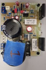
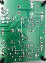
Post a clear photo.
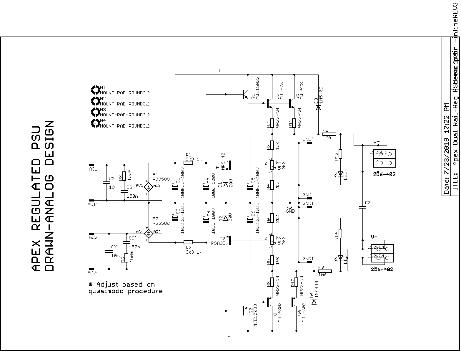
Do not use a trimmer(R8) and a fixed resistor in the same time.
Do not use a trimmer(R8) and a fixed resistor in the same time.
Last edited:
yes a photo of top and bottom will help in identifying the problem better. could also be diodes or other electro components being put in wrong way around.
Last edited:
I shouldn't work late into the night..
Looked at the board this morning and literally took me 2 seconds to realise that I'd left R5 as a To Be Confirmed once I'd run board 1. 😕
Anyway, all stable and happy now.
BTW, R5 was better at 14k for a 48v supply.
Looked at the board this morning and literally took me 2 seconds to realise that I'd left R5 as a To Be Confirmed once I'd run board 1. 😕
Anyway, all stable and happy now.
BTW, R5 was better at 14k for a 48v supply.
One thing I've noticed about these boards, is that C1 is very sensitive and causes buzzing of the output. If I put my finger near or touch C1, it gets louder.
Not sure what to do about that yet.
Not sure what to do about that yet.
I've attached a small video to demonstrate the noise and feedback that I've got on the ax-6.
I wonder if someone can help me out - I've got 2SC5200 as outputs in lieu of MJL4281. Everything else as per ax-6 schematic (except R5=14k).
Are the 2SC5200s unstable in this configuration?
Is there anything in particular spec wise with the 2SC5200 versus the MJL4281 that would indicate incompatibility to someone more experienced?
Can I do anything to make this amp happy with the 2SC5200?
Thanks!!
Attachments
Just coming in late here but my observation is that this PSU is basically an amplifier without any capacitor compensation on the feedback loop. You are not going for audio bandwidth on the control feedback loop so maybe add 22nF film cap across R3 and R5. That should dampen any feedback induced oscillation. Also, I noticed that there is a lack of usual 100nF bypass film caps on all of the larger electrolytic caps. That might help on C1 directly.
I've attached a small video to demonstrate the noise and feedback that I've got on the ax-6.
I wonder if someone can help me out - I've got 2SC5200 as outputs in lieu of MJL4281. Everything else as per ax-6 schematic (except R5=14k).
Are the 2SC5200s unstable in this configuration?
Is there anything in particular spec wise with the 2SC5200 versus the MJL4281 that would indicate incompatibility to someone more experienced?
Can I do anything to make this amp happy with the 2SC5200?
Thanks!!
Hello Avtech,
I do not think 2SC5200 has anything to do with the noise. Some kind of RF being picked up in the i/p section? Due to i/p wiring close to SMPS?
Can you post some images? it could be due to some component in i/p section not soldered properly...
is this problem with both channels or only one channel?
Is this also present when i/p is shorted and not connected to any external source? You could try putting a 100k resistor across i/p terminals and see...
regards
Prasi
Hi Prasi,
I'm not in the workshop at the moment but I'll try and get some pics when I get a chance.
The board is mounted to the heatsink, nothing attached but a test speaker close by and the SMPS about 18in away. The input is not connected to anything.
Both boards behave the same.
I'll try shorting the I/P next.
Hello Avtech,
I do not think 2SC5200 has anything to do with the noise. Some kind of RF being picked up in the i/p section? Due to i/p wiring close to SMPS?
Is this also present when i/p is shorted and not connected to any external source? You could try putting a 100k resistor across i/p terminals and see..
I shorted the input with 100k and still see the same buzzing. About 21mV at the output.
The SMPS is far away and has a shielded cable bringing the power to the board. Only power and speaker are connected and the board is not mounted in a chassis yet, just doing the bench testing still.
That's a tough one to guess. I am guessing, the only recourse would be using a regular linear supply. This might help to identify, if smps is causing the issue. I am saying this because, when i tested with linear supply, it was completely silent.
By shorting the i/p, i meant a jumper across the i/p terminals.
By shorting the i/p, i meant a jumper across the i/p terminals.
You could try putting a 100k resistor across i/p terminals and see..
I tried this suggestion.
I'll have a go at a dead short next time I get to play.
I don't have a 35v transformer but I have a second SMPS so I'll give that a try.
where/how did you connect smps to amplifier board? smps does not like huge capacitors at its output,and you have it on an amplifier pcb.
You can put a cap multiplier in between SMPS and large caps and it works because it slowly ramps up. I often use this cap Mx in between the SMPS (or DC-DC conv) and a cap filter like CRCRC to prevent auto shutdown on the SMPS. Plus, it reduces ripple by additional 50dB. Biggest problem is 4v dropout and heat that comes with it - so have to overspec the voltage (or increase adjustment in case of DC-DC).
where/how did you connect smps to amplifier board? smps does not like huge capacitors at its output,and you have it on an amplifier pcb.
That's an interesting point.
I'll try taking C12 out and see how that affects things.
you also might have neon or other lamp (modern power-saving) at your work desk. I had a lot of trouble finding a reason why I had fat line on my osciloscope - while amp works perfectly stabile and with wide bandwidth. reason was modern power saving light bulb at my work desk,when I removed it and changed for old wolfram light bulb everything was all right. just another guess...
- Home
- Amplifiers
- Solid State
- Retro Amp 50W Single Supply