Hi All,
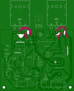
Here is my pcb version on AX6 amplifier circuit with TO246 package power transistors.
https://www.dropbox.com/s/kz2m72offvtio1g/Board_TO246.GIF
PCB for print
https://www.dropbox.com/s/plh3ma156q8g0ug/AX6%20rev_1_6_TO246_PCB_PRINT.pdf
Schematic and Simulation
https://www.dropbox.com/s/f4c109ep479b6aw/sch1.png
https://www.dropbox.com/s/suvoupxhxv0yqtf/sch2.png
https://www.dropbox.com/s/szavhehgng9uhxh/sch3.png
The trimmers on bias and offset are these - https://www.dropbox.com/s/fk05m8ruosaaq9w/SH655MCL _trimers.pdf or Bourns
BR,
Lyubo
Thanks for this files.
Regards
Hi All,
Here is my pcb version on AX6 amplifier circuit with TO246 package power transistors.
https://www.dropbox.com/s/kz2m72offvtio1g/Board_TO246.GIF
PCB for print
https://www.dropbox.com/s/plh3ma156q8g0ug/AX6%20rev_1_6_TO246_PCB_PRINT.pdf
Schematic and Simulation
https://www.dropbox.com/s/f4c109ep479b6aw/sch1.png
https://www.dropbox.com/s/suvoupxhxv0yqtf/sch2.png
https://www.dropbox.com/s/szavhehgng9uhxh/sch3.png
The trimmers on bias and offset are these - https://www.dropbox.com/s/fk05m8ruosaaq9w/SH655MCL _trimers.pdf or Bourns
BR,
Lyubo
Your outputs wrong connect, some pins reverted.
Hello apexaudio!
I have a small question about this amplifier (AX6).
It may be appropriate for a bass guitar amplifier?
The power can be increased by making it four output transistors?
Regards!
PS: I regularly read your very interesting thread. 😉
I have a small question about this amplifier (AX6).
It may be appropriate for a bass guitar amplifier?
The power can be increased by making it four output transistors?
Regards!
PS: I regularly read your very interesting thread. 😉
here is another question for APEX
Do you find any use to run this amp from a regulated power supply ?
Kind regards
Sakis
Do you find any use to run this amp from a regulated power supply ?
Kind regards
Sakis
here is another question for APEX
Do you find any use to run this amp from a regulated power supply ?
Kind regards
Sakis
Yes I was thinking to use a capacitive multiplier
Regards
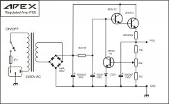
This might work nicely as a power supply for the amp:
Power Supply Replacement
The page includes assembly manual and schematics.
Power Supply Replacement
The page includes assembly manual and schematics.
Close to the Quad 303 power supply.
QUAD 303 PSU and DYNACO ST120 PSU
Attachments

Last edited:
I think both designs may share a common ancestor...the Dynaco Stereo 120 power supply design. Does anyone know when the Quad 303 first went into production?
Hello apexaudio!
I have a small question about this amplifier (AX6).
It may be appropriate for a bass guitar amplifier?
The power can be increased by making it four output transistors?
Regards!
PS: I regularly read your very interesting thread. 😉
For bass guitar use some powerfull amp, AX6 is only 25W at 8 Ohms load.
Regards
The AX6 with the improvements, an idle bias current setting potentiometer, and a center level symmetry improving potentiometer, is beginning to be useful.
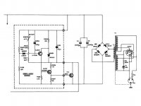
I own an original dynaco ST120. With an original 5 digit RCA TO3 transistor on the PC14 (power supply regulator PWB), it will actually collapse the upper rail voltage if the current out gets above 6.25 Amps (as designed). It collapses the voltage at about 2.5 A with an NTE60 transistor, which has higher gain. All this is fine at a stable temperature, which I encourage with two PCAT fans blowing on the amp- 17 hours a day in most cases. Mine doesn't regulate at 72v, running more like 80 all the time. I don't hear hum, with a shorted input, so I don't worry about the regulation. My speakers are 101 db @ 1W ! m, fairly sensitive.
I think Salas G amp power supply is probably more useful, but no board layouts are available for it. http://www.diyaudio.com/forums/solid-state/229120-g-amp.html
I've bought the parts but have been doing other things, haven't actually built the G amp yet. I haven't been able to keep a *****se made printer cartridge running more than 6 weeks and 40 pages since 1998, so if I build anything it will be point to point on perf board.
With improved heat sinks, 2 fans blowing on the heat sinks, 80 v rail, and NTE60MP output transistors, the ST120 can put out much more than 60 w/ch into 8 ohm for a little while. Not long enough to play guitar on stage though. My average voltage out into 8 ohms is 1.5 Vpp, with 60 db higher peaks as the music reaches its climax.
Last edited:
I think both designs may share a common ancestor...the Dynaco Stereo 120 power supply design. Does anyone know when the Quad 303 first went into production?
1967 per Wikipedia.
using the same source, e.g. Wikipedia, the Stereo 120 dates from 1966...
Quite possible that they used an example from the RCA manual, or from a Wireless World article. Lots of ideas were shared via WW back then. Have a look at Peter Walker's Current Dumping amp article, which became the QUAD 405, then later the remarkably similar Stasis amps.
Yes sir, sorry for the confusion. Here is the corrected version.Your outputs wrong connect, some pins reverted.
Board
https://www.dropbox.com/s/kz2m72offvtio1g/Board_TO246.GIF
PCB for Print
https://www.dropbox.com/s/plh3ma156q8g0ug/AX6%20rev_1_6_TO246_PCB_PRINT.pdf
Regards,
Lyubo
Last edited:
Yes sir, sorry for the confusion. Here is the corrected version.
Board
https://www.dropbox.com/s/kz2m72offvtio1g/Board_TO246.GIF
PCB for Print
https://www.dropbox.com/s/plh3ma156q8g0ug/AX6%20rev_1_6_TO246_PCB_PRINT.pdf
Regards,
Lyubo
No, it's wrong again.
Regards
Sorry, could you please show me where is the mistake now?
Pins reverted
Attachments
Thank you very much sir for the support.
There you go...
https://www.dropbox.com/s/keav10qzief0m4l/Board_TO246.png
and PCB
https://www.dropbox.com/s/plh3ma156q8g0ug/AX6%20rev_1_6_TO246_PCB_PRINT.pdf
This must be a final version 😛
Regards,
Lyubo
There you go...
https://www.dropbox.com/s/keav10qzief0m4l/Board_TO246.png
and PCB
https://www.dropbox.com/s/plh3ma156q8g0ug/AX6%20rev_1_6_TO246_PCB_PRINT.pdf
This must be a final version 😛
Regards,
Lyubo
- Home
- Amplifiers
- Solid State
- Retro Amp 50W Single Supply