You can always look at the datasheet for relevant specifications.
One of the features of Dale CMF resistors is low, controlled temperature coefficient. They publish the specs.
https://www.mouser.com/datasheet/2/427/VISH_S_A0011430496_1-2571893.pdf
One of the features of Dale CMF resistors is low, controlled temperature coefficient. They publish the specs.
https://www.mouser.com/datasheet/2/427/VISH_S_A0011430496_1-2571893.pdf
I don't think I have seen a commercial board with a CMF in over 10 years. Has anyone measured a difference over Yageo in any audio amplifier, DAC, ADC or other audio circuit? (I picked Yageo due to their market share.)
Last edited:
I have found that I like a clean sounding amp. But a second approach is to take advantage of distortions to make a likeable amp. I've moved back and forth between these two camps and finally I find that there is a middle way which suits me best.
Same. But the definition of middle way for you and me maybe is slightly different 🙂
I assume that you might have missed my point. (Unless I am wrong) it is held that standard 1/4W 1% metal film resistors are sufficient for the four examples I gave. I know you are familiar with Groner's Super Op-Amp (you started a thread on that) and I assume you are also familiar with the Hall notch filter or at least another similar notch for measurements.
I would also be surprised if you were not sufficiently familiar with the answers to your questions with regards to either DAC I/V & filter example. But I did attach an example PCM1794 I/V and filter schematic for reference. Both the PCM1794 and ES9038Q2M are very widely known. (So I thought they were reasonable references without going into the details. Honestly an op-amp I/V or the following filter in a DAC are hardly that complex?)
My point (with those four examples) is that 1/4W 1% metal film resistors are sufficient for a number of reasonably demanding examples. If I am wrong please go ahead and explain.
I might have missed that point, yes. I was only reacting to the questions posed, and that reply still stands.
For the 4 examples you gave, yes I agree that no boutique resistors are needed, except with one remark. Some of those resistors have rather low values like 360 ohms. With low frequencies and high level, you might get thermal modulation approaching the overall distortion level.
I don't have a rigorous calculation for this, but my experience-driven mindset would be to increase those values at least to the 1k level.
Jan
That is generally along the lines of what I was trying to get people to think about with my four questions/examples. Instead of just low mV and mW levels with a high value resistor I included relatively well known and well understood DAC I/V and filter examples which are considerably more demanding. (And fairly low THD and noise examples.)For the 4 examples you gave, yes I agree that no boutique resistors are needed, except with one remark. Some of those resistors have rather low values like 360 ohms. With low frequencies and high level, you might get thermal modulation approaching the overall distortion level.
Something can be concluded from the fact that 1/4W or even 1206/0805/0603 are routinely used in commercial (and evaluation boards) for PCM1794, ES9038Q2M and similar. The examples are reasonably accessible to many on the forum and demonstrate that no unusually expensive resistors are needed in these fairly demanding examples. (Usually, generally speaking.)
Getting back to thermal modulation: Does anyone have any ballpark thermal time constant data for CMF (or even more general purpose Yageo/KOA/etc 1/4W 1% metal film)?I don't have a rigorous calculation for this, but my experience-driven mindset would be to increase those values at least to the 1k level.
How about a starter "back of the envelope" calculation for 4.5V, 360 Ohm, 20 Hz and CMF thermal characteristics or similar? I am fond of using "back of the envelope" calculations to improve the basic understanding of an issue.
It would be nice to have at least a basic calculation showing what order of magnitude the thermal modulation might be for a 1/4W metal film. Instead of going to 1k one could also look at 1/2W, 1W or 2W. Ti likely used 360 Ohm and other low values for noise reasons. But I have not seen a report of thermal modulation or more exotic resistors being needed for the PCM1794.
For those that are interested: From the Test Bench: Resistor noise and non-linearity - Audio Precision
Consider the simple resistor. Real world resistors exhibit both thermal and voltage coefficient effects. The first is commonly known as temperature coefficient (or tempco), and usually has units of %/C or ppm/C. It causes gain and bias variations as the operating temperature is varied. Less well known is the fact that temperature coefficient can also result in distortion as the signal causes thermal modulation of the resistor value. This is typically seen at low frequencies where the resistor temperature can begin to follow the changes in instantaneous power dissipation.
Resistor voltage coefficient effects are just as real and can also cause unwanted distortion. Here the typical unit is in ppm/V. Voltage coefficient is a bit more mysterious because few vendors publish data or give a specification. DVM designers are quite sensitive to this effect because it limits accuracy with higher voltage inputs. In the world of audio, this same characteristic can result in measurable distortion at typical line levels. The move towards smaller and smaller components has been insidious because it exacerbates both thermal and voltage coefficient effects. The distortion performance in circuits built using 0402 or 0201 surface mount components will be substantially greater than using larger sizes.
Also see: https://hifisonix.com/wordpress/wp-content/uploads/2017/11/Designing_for_Ultra-Low_THD_N-1.pdf
Last edited:
In the world of audio, this same characteristic can result in measurable distortion at typical line levels. The move towards smaller and smaller components has been insidious because it exacerbates both thermal and voltage coefficient effects
That's an interesting claim, based on sound logic. Has it been measured? Line level is pretty low compared to DVM high voltage inputs.
It also seems like it would be easy to avoid if you weren't constrained by size considerations.
So that quote was from Audio Precision Co-founder Bruce Hofer at the link given. So I would assume that yes they have measured it.
Further if you read the other link (copied again below, especially pages 6-9 (19-22 in the original publication) and the page 1 introduction) it appears to me that these claims are based upon the actual measurements and experience of Audio Precision Co-founder Bruce Hofer.
https://hifisonix.com/wordpress/wp-content/uploads/2017/11/Designing_for_Ultra-Low_THD_N-1.pdf
Well that is very interesting.
I don't doubt the effects of voltage coefficients. I don't doubt that different resistors have different voltage coefficients. I just wonder at what point they become a cause for concern. It is my opinion that conservative design can virtually avoid this issue altogether.
I don't doubt the effects of voltage coefficients. I don't doubt that different resistors have different voltage coefficients. I just wonder at what point they become a cause for concern. It is my opinion that conservative design can virtually avoid this issue altogether.
Audio isn't that hard to get to transparent IMO. Others appear to believe that you need to swap things around to 'season to taste' As the audio industry has relied on that in marketing for at least 40 years now it's ingrained that you can 'voice' a design with a sprinkling of special components . And so the whole subjective/objective cycle starts again.
Very back of the envelope: a resistor with a 50ppm tempco will change its resistance modulated by 0.05% with a delta-T of 10C.
So if this is the feedback resistor, and there indeed is a temp modulation of 10C, you wont get very low distortion.
I know from measurements made by member simon7000 (unpublished) that at low frequencies temperature modulation can be measured. Maybe simon7000 can chime in.
I can attest to the AP views on this, I have several times discussed this at AES meetings with Mr. Hofer. The trick of using 20 resistors in series for the feedback resistor, the same ones you use for the shunt resistor, is another Hofer trick that allowed them to charge $ 35k for an APx555 ;-)
Jan
I was told about that resistor trick in a lecture by an AD guy back in the 80s. I'll see if pdfs are around to stir things up a bit.
Very back of the envelope: a resistor with a 50ppm tempco will change its resistance modulated by 0.05% with a delta-T of 10C.
So if this is the feedback resistor, and there indeed is a temp modulation of 10C, you wont get very low distortion.
I guess the slightly more difficult part of the calculation involves the thermal time constant and the frequency to see how much temperature modulation you will actually get.
See:
- Attached from the following links:
- Resistors – Resistivity, Thermal Resistance and Temperature Coefficient – Passive Components Blog
- https://hifisonix.com/wordpress/wp-content/uploads/2017/11/Designing_for_Ultra-Low_THD_N-1.pdf
I know from measurements made by member simon7000 (unpublished) that at low frequencies temperature modulation can be measured. Maybe simon7000 can chime in.
I saw the "Resistor non-linearity – there’s more to Ω than meets the eye - Ed Simon" PDF but I am not sure if it is ok to share the link. With numbers like -170 (best Dale) to -135 dBc (Xicon) for a wide variety of 1/4W metal film (and 16 Vrms) I am not very concerned about resistor distortion. However I would stay away from small surface mounts and carbon film. I wish he had included more brands and series of 1/4W 1% metal film resistors. I guess Mouser wants about a dollar for Dale and a penny for Xicon. I would be nice to see a few more common brands between those two.
Perhaps in the feedback for one of my power amplifiers I might put a little attention there and perhaps in selecting the power rating and vendor/series for the very best PCM1794 or ES9038Q2M implementation. But even with lots of effort my amplifiers "only" reach about 0.001 to 0.002% THD.
I actually made one PCM1794 with 1/4W metal film (and polyester capacitors) and another with 2W metal film (and CBB capacitors). Unfortunately any difference is below my E-MU 1616m and 1820m measurement capability. I did make a few Hall notch filters but I have not made a super clean generator (yet).
Attachments


Last edited:
A few resistor tests. My standard method.
Attachments

Last edited:
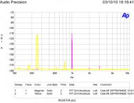
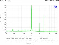
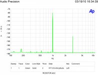
Ed, I was thinking about the measurements on the naked Vishays, wasn't there a clear thermal modulation? I will see if I can find it.
Found it. If you remember, I took your matrix of measurements and sliced it differently, with this result.
So you see that with the same level, but different frequency, the distortion is different, generally higher at some lf range.
(Of course, thermal modulation causes odd harmonics).
Jan
Found it. If you remember, I took your matrix of measurements and sliced it differently, with this result.
So you see that with the same level, but different frequency, the distortion is different, generally higher at some lf range.
(Of course, thermal modulation causes odd harmonics).
Jan
Attachments
Last edited:
A few resistor tests...
Seems to me I was recently chided for not accepting that all metal film resistors measure at -180dB distortion. 🙄
Last edited:
IIRC Bruno Putzey found that the sound just kept getting better as distortions were reduced more and more.
Very back of the envelope: a resistor with a 50ppm tempco will change its resistance modulated by 0.05% with a delta-T of 10C.
So if this is the feedback resistor, and there indeed is a temp modulation of 10C, you wont get very low distortion.
If the thermal time constant of the resistor is 10 seconds and the frequency is 100 Hz how much will this 0.05% modulation be attenuated?
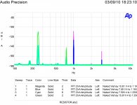
I don't know, but 10 secs seems long for a 1/4W resistor. But look at the graph I posted above, it shows that at some (narrow) freq. range there is clearly distortion. These were $ 20 resistors, I won't tell the brand.
Jan
Jan
Ed, I was thinking about the measurements on the naked Vishays, wasn't there a clear thermal modulation? I will see if I can find it.
Found it. If you remember, I took your matrix of measurements and sliced it differently, with this result.
So you see that with the same level, but different frequency, the distortion is different, generally higher at some lf range.
(Of course, thermal modulation causes odd harmonics).
Jan
That is shown on the first and fifth graph shown above. Also note in the last image as the power increases (applied voltage doubled) the distortion can go up by more!
Last edited:
- Status
- Not open for further replies.
- Home
- Design & Build
- Parts
- Resistor Sound Quality Shootout