These were $ 20 resistors, I won't tell the brand.
Jan
Can we guess? Is it, ummmm, naked Vishay z-foils?
I don't know, but 10 secs seems long for a 1/4W resistor. But look at the graph I posted above, it shows that at some (narrow) freq. range there is clearly distortion. These were $ 20 resistors, I won't tell the brand.
Jan
If someone knows the actual time constants and how to incorporate those (and the frequency) into the back of the envelope calculation please post.
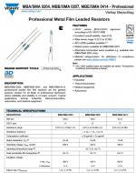
The time constants I found were 2, 5 and 20 seconds and appear to correspond to 0.4W, 0.6W and 1W. However I am not sure which brand or series they refer to. The attached first image has the time constants I found and the DIN size. The second attachment is for high reliability Vishay resistors which are the same DIN size code. If someone has better data please post.
Keep in mind that many modern ADC/DAC recording interfaces (with specifications in the range of -120 dBc and sometimes better) use 0805 size resistors and sometimes 0603 and with very modest cost. (Nothing exotic or expensive looking. Not even any large case sizes.) Often these interfaces are light years beyond what was used to record many of the classic and critically acclaimed compact discs.
For example, inside the Motu M4 I don't recognize any exotic or expensive resistors: Motu M4 - Tear down, bit of internals analysis and few in-house measurements | Audio Science Review (ASR) Forum (But they do appear to use resistor networks, perhaps for the inherent matching?)
Attachments
Last edited:
For metal film resistors, one has to evaluate several lots as during the film deposition, depending on solar flux and the magnetosphere, the conduction band electrons spins can become aligned and generate non-linearities. The spins must be randomly distributed to avoid this. Multiple listening sessions and manufacturing lots have confirmed it.
Do I dare post such nonsense and create another 20 pages of discussion. I did, so I am the dumb one.
Do I dare post such nonsense and create another 20 pages of discussion. I did, so I am the dumb one.
@kozard: let us not forget that the actual position of the R in the circuit is critical. Much different for a feedback resistor or, for example, a current source setting resistor.
Jan
Jan
Do I dare post such nonsense and create another 20 pages of discussion. I did, so I am the dumb one.
Thanks for the heads-up!

Jan
@kozard: let us not forget that the actual position of the R in the circuit is critical. Much different for a feedback resistor or, for example, a current source setting resistor.
Jan
Agree.
Lacking distortion measurements or data for the metal film resistors I have instead used a 2W metal film for the feedback resistor in my recent amplifiers. However I would not be shocked if that turns out to be unnecessary. But it is an easy way to ensure what is likely to be plenty of margin.
I don't really want to put 10, 20 or even 30 resistors in series... Swapping a 1/4W for a 2W seems like a more elegant way to see if there is anything to be gained.
Since I have not seen any THD changes from 1/4W to 2W feedback resistors I doubt it is remotely a limiting factor anyways. My 0.001 to 0.002% THD uPC1342V power amplifier still uses a 1/4W 1% metal film feedback resistor. I certainly don't see 0.05% THD type issues.
So with 1/4W versus 2W experiments I have not seen a difference with my power amps (feedback resistor), DAC (I/V and filter) or my Hall notch filter. I believe that I would need a considerably better measurement capability to see anything.
Last edited:
Very back of the envelope: a resistor with a 50ppm tempco will change its resistance modulated by 0.05% with a delta-T of 10C.
So if this is the feedback resistor, and there indeed is a temp modulation of 10C, you wont get very low distortion.
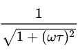
Any chance that 1/Sqrt[1+(wt)^2] would be the correct factor to attenuate the 0.05% for periods (frequencies) much shorter than the 2 to 20 second thermal time constants for leaded resistors? (Assuming that those time constants are correct.)
Surely someone remembers the equations.
Attachments

I remember those and a whole lot more. Makes no difference because they hear the difference. Good for them, but for me physics and even psychology trump that when searching for the truth.
Why do I feel the need to continue to stir the pot??????
Why do I feel the need to continue to stir the pot??????
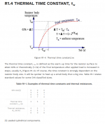
Thermally Induced Resistor Distortion
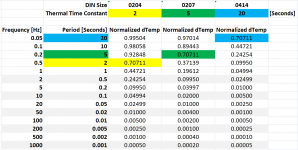
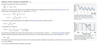
Using the previously posted formula (for a first-order, linear time-invariant system) I made the attached chart for the 2, 5 and 20 second thermal time constants that I found online for leaded resistors in three DIN sizes. I don't know if the time constants correspond to the attached Vishay resistor series or a different brand/series of those three DIN sizes. The Vishay resistors are rated 0.4W, 0.6W and 1W for the three DIN sizes.
If anyone knows of an error in either the application of that formula or the thermal time constants please post a correction and an explanation.
From these calculations would it be correct to say that there should be very large reductions in thermally induced resistance change and distortion ["thermal modulation"] due to the very large difference between the (short) periods of audio frequencies and the (long) periods of the thermal time constants?
Attachments


Last edited:
Who cares?Bruno Putzey found that
If he proved something, then many should care.
I think he interpreted 'found' incorrectly. When Bruno says, 'I found', he means the outcome of a well documented and structured experiment leading to facts.
Jan
Jan
Using the previously posted formula (for a first-order, linear time-invariant system) I made the attached chart for the 2, 5 and 20 second thermal time constants that I found online for leaded resistors in three DIN sizes. I don't know if the time constants correspond to the attached Vishay resistor series or a different brand/series of those three DIN sizes. The Vishay resistors are rated 0.4W, 0.6W and 1W for the three DIN sizes.
If anyone knows of an error in either the application of that formula or the thermal time constants please post a correction and an explanation.
From these calculations would it be correct to say that there should be very large reductions in thermally induced resistance change and distortion ["thermal modulation"] due to the very large difference between the (short) periods of audio frequencies and the (long) periods of the thermal time constants?
My check point is the outcome of tests which clearly show an effect as shown before. I don't know how to reconciliate that with the theoretical side.
Jan
Well I’m puzzled - I have Borbely jfet dac, line, and phono preamps built with naked Vishays. Occasionally i hear what I think is a thickening in the low frequencies, but overall the best feature of the resistors seems to be great low level detail. Hard to reconcile with the measurements. I have built the same circuits with Dale RN 60, but find the sound a little sterile and not as involving compared to the TX 2575. Ed’s test at 7.5 and 15 volts show the naked resistor’s distortion is level dependent. What is it at the more typical 2 volts? although clearly not a resistor for a power amp.
I think he interpreted 'found' incorrectly. When Bruno says, 'I found', he means the outcome of a well documented and structured experiment leading to facts.
Jan
I think this was taken from an interview with Bruno I read where he commented that the lower the distortion the better things sound. More a statement of his design drivers. BUT should be noted Bruno uses the right part in the right place and has no truck with Flooby dust amplifier voicing.
Seems to me I was recently chided for not accepting that all metal film resistors measure at -180dB distortion. 🙄
Please repeat these measurements at a few mW. I remind you most reference designs and demo cards use ordinary 0805 or even smaller SMT resistors and often equal the floor of the AP. And yes I made one of our techs do several parallel/series resistor configurations on the output buffers with no measurable effect (>.25dB). The feedback resistor in a PA is a very tired horse.
So it is still up to you to provide the refereed listening tests using the published protocol that Jacob posted. And the listeners should be trained as specified, coaching them to hear what you think they should hear is not acceptable.
Shouldn't this thread being merged with the Funniest Snake Oil theories one 😀? I think all has been said there yet.
Best regards!
Best regards!
Scott,
I don't doubt you measured vanishingly low resistor HD in laboratory conditions.
However I will disagree on some other points. I don't accept that HD is the only audible effect to look for. As I have said before, linear distortions can sometimes be audible. Also, different types of noise sound different to humans. Signal correlated noise may be something else to consider. IMHO it is myopic to only look for HD and baseline noise magnitude.
Also, regarding coaching people on what to listen for, I disagree that it should be unacceptable if trained people can then perform better in well-conducted blind testing. Blind test results should show whether coaching is useful and effective or not.
Well I’m puzzled - Ed’s test at 7.5 and 15 volts show the naked resistor’s distortion is level dependent. What is it at the more typical 2 volts? although clearly not a resistor for a power amp.
Probably down another 30 dB or a bit more. Well below the noise floor except at very low frequencies.
Also, different types of noise sound different to humans. Signal correlated noise may be something else to consider.
Excess noise in resistors also goes as V squared in general. I'm sure there are many DAC's/A to D's with mechanisms far worse. Someone needs to ride their hobby horse in that direction.
By training I meant by someone biased toward a certain result. There are processes for unbiased training to hear small impairments.
Last edited:
- Status
- Not open for further replies.
- Home
- Design & Build
- Parts
- Resistor Sound Quality Shootout