If is is possible, perhaps it could be a switchable option. This feature is present on some high end preamps and can be useful when muting and unmuting at loud levels.
Once you've muted while listening at loud levels, and then you un-mute after a period, your ears are not ready for the loud sound. There are small muscles in the ear that dampend loud sounds and they relax so-to-speak when it is quiet; the loud un-mute makes them suddenly go to work. If it is switchable, then one could make their own choice.
Once you've muted while listening at loud levels, and then you un-mute after a period, your ears are not ready for the loud sound. There are small muscles in the ear that dampend loud sounds and they relax so-to-speak when it is quiet; the loud un-mute makes them suddenly go to work. If it is switchable, then one could make their own choice.
Mute
Would it be an idea to have the mute function as a -10 or -50 step for volume , (adjustable?), with an adjustable lower limit?
Arne K
Would it be an idea to have the mute function as a -10 or -50 step for volume , (adjustable?), with an adjustable lower limit?
Arne K
rljones said:... This feature is present on some high end preamps ....
Alas, most high-.end pre-amps don't use high-end volume control methods such as Apox relay variants.
Petter
Personally, I prefer to get back to the same volume level as the mute is switched off. This is the whole purpose of this switch: you had your volume carefully adjusted to a certain level, and suddenly a phone rings and you have to talk, so instead of using volume knob to turn the volume down you use a switch, so it doesn't mess up your adjustments.
Now an interesting feature would be coming up to the loud level smoothly, with volume increasing slowly. Is this possible?
Now an interesting feature would be coming up to the loud level smoothly, with volume increasing slowly. Is this possible?
Peter Daniel said:
Now an interesting feature would be coming up to the loud level smoothly, with volume increasing slowly. Is this possible?
That sounds like a GOOD feature!!!

It would have to store the last volume setting in memory when mute is pressed, and then do the binary counting from zero to the saved value at a specified rate (ex. 6 steps up per second).
I can see how this can be tedious for Dale as every volume board has different relay configs

Poor Dale, didn't know what he was getting himself into

-Vinnie
Petter, Vinnie, Peter,
This IS what I meant in my earlier post on feature 2 about 'ramping' up the volume: the mute zeros it, and un-mute ramps rapidly up to the previous setting. It avoids the sudden un-mute. (I guess I don't write clearly enough.)
Robert
This IS what I meant in my earlier post on feature 2 about 'ramping' up the volume: the mute zeros it, and un-mute ramps rapidly up to the previous setting. It avoids the sudden un-mute. (I guess I don't write clearly enough.)
Robert
For me this is not important, but let me suggest a possible resolution (which really needs to be possible to disable!):
Step up in say 5-8 steps over a couple of seconds (i.e not smooth). Do all the switching using the same "range" to avoid troublesome transients (particularly SHM type).
If this staircase model is acceptable, I guess it MIGHT ne possible to have it implemented.
Petter
Step up in say 5-8 steps over a couple of seconds (i.e not smooth). Do all the switching using the same "range" to avoid troublesome transients (particularly SHM type).
If this staircase model is acceptable, I guess it MIGHT ne possible to have it implemented.
Petter
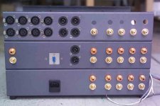
Rear Panel of monster preamp. Inputs are: bottom chassis for surround; middle chassis for center and sub/height and balanced center output; top chassis for 4 balanced inputs and 4 s.e. inputs for front left and right channels. Also in middle chassis are RS232 access from rear and left of that are 2 s.e. for tape out from front channels.
Attachments
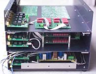
Power supply in bottom chassis. One for 5VDC for APOX boards, one for surround and center gain stage, and one for front left and right channels. The audio power supplies are R-C-L-C-R-C design with a common mode inductor on the AC input along with ferrite bead filtering on AC inputs. Rectifiers are MSR1560 in a dual bridge configuration with ferrite beads on one leg of each diode, giving +/- 22VDC. Transformers are 30VA (6VAC @ 5A) and 260VA.
Attachments

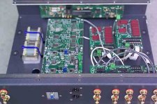
Inside middle chassis with IR1 on front panel; IS1s on the rear at bottom of image; SHMs on the right (there will be 4 on this layer; two for bottom inputs and two for the inputs on this layer); and gain stage boards on the left. To the far left are 2 Jensen output transformers that I may use for generating a balanced output for the center channel from the s.e. inputs. These are normally used in PCB, and are left over from another project; I've got them here in a 'dead bug' configuration.
Attachments
I built the controller + the first SHM board today. No problems at all, and I was VERY impressed, especially after having played with the controller + display. Wow! I can also report on the physical latching-noise on the SHM relays. There is no noise - you pretty much have to put your ear close to the relays to hear any clunky noises.
Mr rljones, we are in awe. You and I are doing similar things - except you have already done it!
Petter
Mr rljones, we are in awe. You and I are doing similar things - except you have already done it!
Petter
APOX-SHM testing
Due to some issues with Robert's very large system, Craig and I decided to do a big test to make sure a large system would work.
1) We discovered that three of Robert's six boards had a microcontroller that had a good program, but bad configuration registers. We are not sure how this happened, but are glad that this was the cause of the "self resetting".
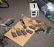
2) We connected 8 SHM, 2 IS1, and one IR1 together to make sure that the I2C would work correctly. As pictured below, the system works fine. We tried to break it, to no avail.
Robert,
Your system is awesome!!!
Best Regards,
Dale
P.S. If you are still having troubles with the IS1's, please send them back and we can add them to this test.
Due to some issues with Robert's very large system, Craig and I decided to do a big test to make sure a large system would work.
1) We discovered that three of Robert's six boards had a microcontroller that had a good program, but bad configuration registers. We are not sure how this happened, but are glad that this was the cause of the "self resetting".
2) We connected 8 SHM, 2 IS1, and one IR1 together to make sure that the I2C would work correctly. As pictured below, the system works fine. We tried to break it, to no avail.
Robert,
Your system is awesome!!!
Best Regards,
Dale
P.S. If you are still having troubles with the IS1's, please send them back and we can add them to this test.
Attachments
IS1 update!!!
Robert,
We were finally able to duplicate your IS1 problem. One of my boards exhibited the same problem after about 20 power cycles. We loaded the configuration and found another bad setting. We corrected the setting and cannot get the board(s) to fail. Here were the symptoms:
1) The IS1 board would start up with the LED on and stay that way. The whole system would not work.
2) The IS1 board would blink rapidly. Other boards worked fine.
3) The IS1 board did nothing. Other boards worked.
So, there seemed to be several failure modes linked to the same config problem. We will burn new chips and ask that you replace the ones you have and send us back the old ones.
We apologize for these issues and in defense, we can point to the Microchip environment that seems to allow multiple hidden configuration windows and randomly uses one of them. Now, we make sure and close all config windows except for one. We will also read back and verify the settings.
One other builder (DB) had a similar problem with an APOX-1 board. Luckily, these problems are easily solved with a chip swap.
I am airing our dirty laundry to make sure that no one else is having troubles with a board and is hesitating to report any problems. Plus, it helps to show that we really care that all systems get going.
Also, some shipments have been delayed pending the outcome of these tests. Craig and I now feel comfortable to ship out the pending orders. Here are the initials of those still left to ship:
AK, RW, JPP (All are from Europe)
Best Regards,
Dale
Dale and Craig:
Thanks for all the hard work. I really appreciate all of your help.
Once I get this surround preamp going, I'm using my second IR1 to make stereo unit for our bedroom (of course, I'll need to buy more IS1s....)
*******
To the rest of the forum:
These two are truly hard-working, honest guys who've put in a tremendous effort to help resolve various glitches in the monster preamp---to say nothing of all of their initial work getting the APOX products up and running.
They've now solved the problems of multiple APOX boards being used simultaneously. What was happening was that a stereo system worked well, but as the complexity increased to 4 channels, sporadic failures would occur with various boards not working and then working the next time the unit was powered up.
The ones that worked sound amazing, and the convenience of a fully remote controlled surround preamp with multiple inputs is one I'm eagerly awaiting.
(BTW, one early problem I had was insufficient capacitance on my digital power supply, by adding 1800uF after the LM150 regulator--seen on the power supply image above with its 30W heat sink in the upper right corner--the supply became very stable. This supply is based on the LM150 data sheet using a few resistors and a potentiometer to get 5VDC.)
Thanks again guys, Robert
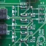
Image of IS1 with jumpers in place of K9-K11 for those who don't wish to use Home Theater Bypass. I had some issue with hum that was improved when K9 was removed. By using these jumpers, all normal connections as described in the IS1 manual will work.
-Robert
-Robert
Attachments
User Manual Updates
Hello all,
The user manuals have been updated for the
APOX-SHM and the APOX-IS1.
Thanks,
Craig Beiferman
Hello all,
The user manuals have been updated for the
APOX-SHM and the APOX-IS1.
Thanks,
Craig Beiferman
Craig,
It has been fun watching the APOX development - apparently great stuff and very well done !
We are four folks in Germany (near Munich) and are building various Pass equipments - Onos (done), Aleph 5s (some done, some in work) and four Aleph P1.7. We have implemented the original Pass volume circuit together with the control logic from Jens Witte (posted in the forum) and a homegrown backplane with relais controlled input selection.
We now would like to use your APOX (core system) with our P1.7s to get remote control and the cool display...
How much effort would it be to add the required functionality to drive the eight relais for the NP volume control and the five relais for input selection ? Is it necessary to wait for the APOX4U currently under development or is there another way ?
Please let me know how we could proceed
Thanks and best regards,
Andreas
Hi Andreas,
I made a special version of APOX-2 and IR1 software for someone in Austria that had a similar need. He used the relay drive outputs to control an already built volume/input select system. The same could work for you with some minor changes.
We would need to charge a small NRE fee. You would only need the APOX-2 board with a small number of components, so we could offer a cheaper version without the relays.
Best Regards,
Dale
- Status
- Not open for further replies.