Dale 🙂bulb:  )
)
thanks for the fast reply - this sounds interesting. I will contact you via email for further details.
Thanks again,
Andreas
) thanks for the fast reply - this sounds interesting. I will contact you via email for further details.
Thanks again,
Andreas
Question :
I have these Alps encoders, can they be used?
(do not know type or model-nr).
-and I would need help about connection...
Where can I find info about encoders, (FAQ), I have never used them before.
It would also been great if the "dipchip-web" had been formatted for printing...
As a last Q: Where do I find a FAQ about all Volume-types, wich to use where, etc..
Arne K
Attachments
Arne,
I don't know about the ALPS encoders.
(I would need a part number)
Do they also feature a push button?
Circuit cellar just had an article about encoders here:
ROTARY ENCODERS
I hope that helps.
Please keep us up to date on your project.
Dale has been on a two week vacation, and I've been swamped at work. So I hope people don't think we are abondoning the project.
Thanks,
Craig Beiferman
I think the Alps is the same as this: http://www.diyaudio.com/forums/showthread.php?postid=146821#post146821
Yes, it has push-button.
And it has a much better feel than the plastichill encoder.
Arne K
Yes, it has push-button.
And it has a much better feel than the plastichill encoder.
Arne K
Hi Arne,
Have you fired up the boards yet?
The alps encoders should work fine. The encoder interface is fairly simple. I assume that the alps is a mechanical encoder, so the RC filter would be required (all parts are supplied). I don't know how many transistions per rotation.
There is no set advice on which volume control to use. A tube preamp may require a constant impedence (apox-2), but you can put the volume control before the preamp gain stage. If you want the volume before the gain, just make sure that your sources can handle a varying load (most can within reason).
or, juts try them. If you notice loss of dynamics, it may be a bad choice...
Dale
Yes, I have powered them...all seem ok.
Still soldering input PCB's...
About encoders, will amount of trancisions/dents pr turn do any difference?(other than feel of control?).
About volume control, as there is so many choices, you shuld make a recomendation for your different versions...
I will use / try a lot of different linestages...(no tubes)
-more like Aleph P, BOSOZ/BLS, Borbely....
Arne K
Hi Arne,
You are correct. The number of detents only affects the feel. The software does not care.
To some degree, the choice of the various versions comes down to personal conviction. Some people like a constant impedence for their sources or gain stage, while others like the shorter signal path of the shunt version. Some circuits will only work within a certain range of impedence, so a constant one is required while other could care less.
The problem is that there are so many different circuit designs and it would be impossible to give a guide that works for everything. The best solution would be to post an email to us or to post one to the great minds at diyaudio.
Best Regards,
Dale
P.S. Congrats on a successful build!
the URL will download a pdf file on the alps encoder; RK09710EL002. (The shaft looks different, but the product number is same as in referenced thread.) while it's in japanese, the specs are understandable.
http://www3.alps.co.jp/pdf/2003pdf/pdf_e/Switch/Encorder/rk097.pdf
so, dale are we home now? I hope you had a good trip.
regards, robert
http://www3.alps.co.jp/pdf/2003pdf/pdf_e/Switch/Encorder/rk097.pdf
so, dale are we home now? I hope you had a good trip.
regards, robert

More Q:
Apox 3 and Apox IS2 seems interesting, for a multi-channel setup.
Can the Apox IR1 drive different volume-boards at the same time?
(Like 2 x Apox SHM + 2 x Apox 3)?
How is the Apox DK1 development?
Will this also control input-boards? Will it be a single (toggle)switch, or (my preference) a switch for each input?
For a Aleph P, (or BOSOZ) with volume after driver-board, what would be the preferred impedance?
Arne K
New software version
Hi APOX users.
A new version or IR1 firmware is on the website. Here are the changes:
1) If in Mute mode, "MUTE" displays after menu and input changes.
2) Support for > 4 inputs fixed.
Best Regards,
Dale
Hi APOX users.
A new version or IR1 firmware is on the website. Here are the changes:
1) If in Mute mode, "MUTE" displays after menu and input changes.
2) Support for > 4 inputs fixed.
Best Regards,
Dale
A question for Dale.....
Hi,
i have a question about Apox 1 board:
In the kit list for Apox1 10k resistorpackage are R13 and R1 double.
One time it is 100k and one time it is 8,25k, so whats true?
And what value is for R34 and R36?
R32 and R33 is optional, why?
Thanks
Reinhard
Hi,
i have a question about Apox 1 board:
In the kit list for Apox1 10k resistorpackage are R13 and R1 double.
One time it is 100k and one time it is 8,25k, so whats true?
And what value is for R34 and R36?
R32 and R33 is optional, why?
Thanks
Reinhard
Hi Arne,
would be that the two boards have a different number of actual
volume steps, so it might be hard to keep them tracking together.
Reinhard, Did you get my email response to the above question, I think I spent 20 minutes writing you a response, and giving you the whole table of values. I'll try to post the resistor values on the web sometime today. But you could compare the APOX-SHM board resistors, and just note the schematic is identical, but the
Reference designators are different.
-Craig Beiferman
It could work with special software, but currently the problemCan the Apox IR1 drive different volume-boards at the same time?
(Like 2 x Apox SHM + 2 x Apox 3)?
would be that the two boards have a different number of actual
volume steps, so it might be hard to keep them tracking together.
It was going along nicely, but then was recently stopped when Dale and I got a whole bunch of contracting work.How is the Apox DK1 development?
Will this also control input-boards? Will it be a single (toggle)switch, or (my preference) a switch for each input?
I have to refer this to Dale, But I think you want the lowest impedance you can get away with. I think he used 5K.For a Aleph P, (or BOSOZ) with volume after driver-board, what would be the preferred impedance?
Hi,
i have a question about Apox 1 board:
In the kit list for Apox1 10k resistorpackage are R13 and R1 double.
One time it is 100k and one time it is 8,25k, so whats true?
And what value is for R34 and R36?
R32 and R33 is optional, why?
Thanks
Reinhard
Reinhard, Did you get my email response to the above question, I think I spent 20 minutes writing you a response, and giving you the whole table of values. I'll try to post the resistor values on the web sometime today. But you could compare the APOX-SHM board resistors, and just note the schematic is identical, but the
Reference designators are different.
-Craig Beiferman
Hi Craig,
> Reinhard, Did you get my email response to the above question
no, i got no email 🙁
Could you copy & paste and send it to r.wolf@ndh.net ?
Kindest regards
Reinhard
> Reinhard, Did you get my email response to the above question
no, i got no email 🙁
Could you copy & paste and send it to r.wolf@ndh.net ?
Kindest regards
Reinhard
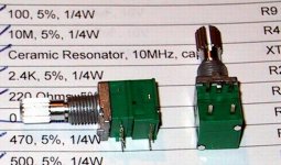
I've done some research on an alternative encoder, and found one that works.
The Digikey number is 102-1019-ND and are $48 apiece. The manufacturer is Tosoku-CUI Stack; part number is RE21NC25C20RA. This one comes with flying leads (5 of them; there are 6 pins on the Greenhill encoder, but 2 of things are shorted together on the IR1 board and both lead to ground).
The shaft is 20mm long and metal, so it is more robust. It is 6 mm in diameter so fits large, heavy knobs like those from DACT (boooo !!!). The clicks are quieter. It too has a switch feature.
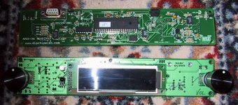
I mounted the IR1 using the holes at the corners of the board using 7/8" standoffs. I have the display on 3/8" standoffs.
I soldered the leads on this unit (pins 1 to 5) to those on the IR1 board (reverse order: pins 6 to 2; the two ground pins 1,2 are the same). I use the same unit for the selector and the volume. The only problem I have with it is that the output is at 25 cycles and the selector is at 16, so it changes inputs rather rapidly.
Dale, perhaps through software, we can adjust the rates of read-out from the encoders, and slow things up a bit?
Regards, Robert
The Digikey number is 102-1019-ND and are $48 apiece. The manufacturer is Tosoku-CUI Stack; part number is RE21NC25C20RA. This one comes with flying leads (5 of them; there are 6 pins on the Greenhill encoder, but 2 of things are shorted together on the IR1 board and both lead to ground).
The shaft is 20mm long and metal, so it is more robust. It is 6 mm in diameter so fits large, heavy knobs like those from DACT (boooo !!!). The clicks are quieter. It too has a switch feature.
I mounted the IR1 using the holes at the corners of the board using 7/8" standoffs. I have the display on 3/8" standoffs.
I soldered the leads on this unit (pins 1 to 5) to those on the IR1 board (reverse order: pins 6 to 2; the two ground pins 1,2 are the same). I use the same unit for the selector and the volume. The only problem I have with it is that the output is at 25 cycles and the selector is at 16, so it changes inputs rather rapidly.
Dale, perhaps through software, we can adjust the rates of read-out from the encoders, and slow things up a bit?
Regards, Robert
Hi Robert,
I am sorry that I didn't respond to your email yet.
My bad, I thought that I was waiting on you for clarification on the changes required for your system. I think that I may need to make custom software for your IS1's/SHM, so that you can have different SE/BAL settings for each unit dependant on the input selected.
Best Regards,
Dale
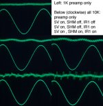
Below is a collage of images I made of oscilloscope shots of my surround preamp's signals. The signal is either 1kHz or 10kHz from an HP 339 distortion analyzer.
The reason I'm posting this is I was getting crazy THD readings from the preamp, yet I knew my gain board and associate power supply were very clean with low THD and wonderful sonics.
I recently got to thinking there was a problem with the digitial power supply corrupting the signal, so I progressively studied the situation and found there appears to be other sources contaminating the signal.
But first some background on the gain stage. The preamp gain stage is discrete and is set for 2x gain. It clips at 17V RMS output. Power supply is well filtered: AC -> ferrite beads -> common mode choke -> soft recover diodes with ferrite beads -> C-L-C-R-C (22V) -> local regulation to +/-18V on each gain stage board. THD of the gain stage at 1kHz is 0.007%, at 20kHz, 0.020%; at 100kHz, 0.090% when used by itself (no APOX circuitry); primarily 2nd order. Noise is about 35 microvolts. This figures are derived with a 600 ohm load of the oscilloscope and 1V output. Input impedance is 1M; output approx 10 ohms.
The 5V digital supply is essentially a wall wart that is rated at 2.8A that I placed in the chassis (bottom layer). The AC is hard wired to its input. I fused it's output so when the fuse is removed, I can check it's affect on the signal but without a load on the digital supply.
My APOX topology is: signal -> IS1 in -> SHM -> gain stage -> IS1 out. Where the images says preamp only, the signal entered the preamp board directly without any potentiometer or IS1 board. In this case, the preamp power supply was on, but the digital 5V supply and all APOX boards were off.
To better describe the images: upper left is gain stage (preamp only) at 1kHz. Below all images are at 10kHz, going clockwise starting at left (left side, middle image):
Gain stage only;
Gain stage + 5V digital power supply on but without load (IR1/SHM both off; IS1 not used, it was off too);
Gain stage + 5V digital power supply on IR1 and IS1 on, SHM off (bypassed);
Gain stage + 5V digital power supply on and all APOX boards all functioning.
Interestingly, the 5V digital supply even without a load does contaminate the signal as seen on the THD plot. Thus, despite my trying to minimize garbage getting into the gain stages power supply, it still gets in. I may either need to re-locate it from the chassis, or go back and change it to a linear style supply. This is not where I need help.
Where I need help comes next. Unfortunately, as shown in the lower righthand image, it would seem that the SHM board also adds to the THD with some very high frequency peaks being added to the THD signal. The only difference between the lower righthand plot and the one immediately to its left, is the signal is being routed through the SHM, whereas the image on the left the signal bypasses the SHM but is still routed through the IS1 board.
So, my question is, how is the SHM contributing this added distortion and how to cure it?
Thanks for any help, Robert
Attachments
- Status
- Not open for further replies.